Fiber optic access network WAN connection topology design
May 25, 2023
Compared with the previous WAN access methods, the fiber optic access network introduced here is obviously different, as it is no longer an access method, but a separate category that is completely distinct from the previous access methods. This is because it no longer transmits electrical signals in the line, but instead uses optical signals. As a result, the fiber optic access network entails a completely different variety of equipment and operates as a self-contained system. There are various access methods within the fiber optic access network. This section provides a general describes of them.
The topology of a fiber optic access network is the structure of the transmission lines and nodes, which indicates the mutual location and interconnection layout of the nodes in the network. In fiber optic access networks, there are three main basic network topologies are bus, ring and star. However, in large networks, some hybrid topologies can also be derived, such as bus-star structure, tree, double-ring and other combinations of applications, each with its own characteristics and complement each other. In this section, we only briefly introduce the above three basic fiber access network topologies. Note that the network structure presented in this section is the most basic modular structure, but the actual fiber optic network also involves many devices and equipment connections.
1. Bus-type architecture
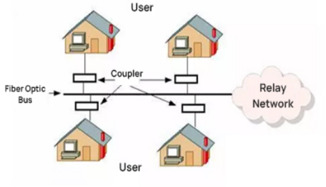
The bus-type structure is a very common topology for fiber optic access networks, which uses optical fiber as the common bus, one end is directly connected to the service provider’s relay network, and the other end is connected to each user. Each user terminal is directly connected to the fiber optic bus through some kind of coupler, and the connection between the user computer and the bus can be coaxial cable, twisted pair cable, or fiber optic. This is similar to the bus-type topology we introduced in LAN, as shown in Figure 1. One of the relay networks can be any of them like PSTN, X.25, FR, ATM, etc. The Cable MODEM access method we introduced earlier uses such an access method.
Figure 1
This structure is a tandem structure, and its advantages include sharing the backbone fiber, saving line investment, easy addition and removal of nodes, and less interference with each other. However, its disadvantages is that it shares the transmission medium, and the connection performance is affected by the number of users.
2. Ring structure
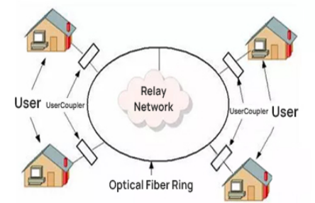
The ring structure is similar to the ring topology in LAN, which means that all nodes share one fiber ring link. The first and last fiber links are connected to form a closed loop network structure. Of course, one end of the fiber needs to be connected to the relay network of service provider. The connection between the users and the fiber ring is also established through various couplers, and the transmission medium used can be coaxial cable, twisted-pair cable, or, of course, fiber.
Figure 2
The outstanding advantage of this architecture is that the network has self-healing capacity, which means that without external intervention, the network can recover from the failure of the service in a relatively short period of time. The disadvantage is that the connection performance is poor, because it also shares the transmission medium. Therefore, it is usually suitable for fewer users in the access network; and the failure rate is high, the failure can have a wide-ranging impact. If the fiber ring is broken, the whole network will be interrupted.
3. Star structure
The star structure mentioned here is the same as the “star structure” in LAN, but the emphasis here is on the transmission medium of optical fiber instead of twisted-pair cables. In this fiber optic access network with a star structure, each user terminal exchanges information through a star coupler with control and switching functions located at the central node (in the end office). It is a parallel structure, there is no loss accumulation problem, easy to realize the upgrade and expansion. Each user is relatively independent, providing good service adaptability. However, the disadvantage is the requirement for more optical fibers (one for each user) resulting in higher costs; in addition, in this structure, all nodes need to go through the central node’s data to connect to the relay network, resulting in a heavy workload for the star coupler at the central node and a heavy requirement for reliability. If the central node fails, the whole network will also be paralyzed.
The star structure is divided into three types: active single-star structure, active dual-star structure and passive dual-star structure.
(1) Active single-star structure
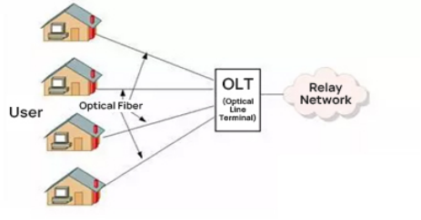
This structure uses optical fiber to directly connect the OLT located in the service provider’s switching office to the subscribers, point to point connection, which is basically the same as the existing twisted copper LAN star structure. In this structure, each household has a separate pair of lines directly connected to the OLT at the service provider’s bureau connected to the trunk network. The basic structure of network access is shown in Figure 3.
Figure 3
The advantages of this structured access method are mainly manifested in the independence and confidentiality among users. It is easy to upgrade and expand capacity, as new services can be enabled by simply replacing the equipment at both ends. This method exhibits excellent adaptability. The disadvantage is that the cost is too high. Each household requires a separate pair of optical fiber or a fiber (two-way WDM). To serve thousands of households, it would require thousands of cores of fiber optic cable, which can be difficult to deal with. Additionally, each household requires a special light source and detector, making the setup quite complex.
(2) Active double-star structure
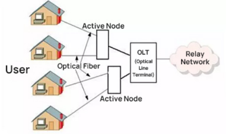
The dual-star structure is actually a tree-type structure with two levels. It adds an active node between the service provider switching office OLT and the subscriber. The exchange bureau and the active node share the same fiber, and use time division multiplexing (TDM) or frequency division multiplexing (FDM) to transmit larger capacity information to the active node and then switch to smaller capacity information streams to reach thousands of households. The basic network structure is shown in Figure 4.
Figure 4
The advantages of this network structure are more flexibility, shared fiber between active nodes in the central office, and reduced fiber optic cable core requirements, resulting in cost reduction. However, the disadvantages are the complexity and high cost of the active node component, making maintenance inconvenient. In addition, introducing new broadband services and upgrading the system would require replacing all optoelectronic equipment or implementing a more challenging WDM overlay scheme.
(3)Passive double-star structure
This structure maintains the advantages of fiber sharing in an active dual-star structure , but instead of an active node, it utilizes a passive splitter. This results in easier maintenance, higher reliability, and lower costs. With the implementation of various measures, the confidentiality is also enhanced, making it a better access network structure.
4. EPON WAN connection topology
EPON network adopts a point-to-multipoint topology to replace the point-to-point structure, which greatly saves the amount of fiber and management cost. Passive network devices replace repeaters, amplifiers and lasers used in traditional ATM/SONET broadband access systems, reducing the number of lasers required at the central office, and the OLT is shared among multiple ONU users. Moreover, EPON uses Ethernet technology and standard Ethernet frames to carry the current mainstream services – IP services – without the need for any conversion. Therefore, EPON is straightforward, efficient, and has low construction cost and maintenance costs, making it highly suitable for broadband access network requirements.
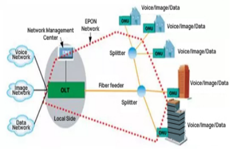
A typical EPON system is also composed of OLT, ONU, and ODN, as shown in Figure 5.
Figure 5
The OLT is placed in the central server room, while the ONU serves as the client-side equipment. In addition to offering network centralization and access, the OLT can also provide bandwidth allocation, ensure network security and management configuration for different user QoS/SLA (Service Level Agreement) requirements. Splitter has a split rate of 2, 4 or 8 and can be connected at multiple levels. In EPON, the distance from the OLT to the ONU can be up to 20km, and it can be further extended if a fiber amplifier (active repeater) is used.
As shown in Figure 5, the optical signal is split into multiple channels for each optical network unit (ONU) through an optical splitter, and the upstream signal from each ONU are combined in a single fiber using an optical coupler and sent to the OLT. Passive network equipment includes single-mode fiber optic cables, passive optical splitters/couplers, adapters, connectors and fusion splicers. It is generally placed outside the local area and referred to as external equipment. Passive network equipment is very simple, stable, reliable, long-lasting, easy to maintain, and cost-effective. Active network equipment includes central office rack equipment, optical network units, and equipment management systems (EMS). The central office rack equipment comprises fiber optic line terminals, network interface modules (NIMs), and switching modules (SCMs). Therefore, these three types of equipment are collectively referred to as central office rack equipment.
The central office rack equipment serves as the interface between the EPON system and the service provider’s core data, video, and voice networks. It is responsible for connecting to the service provider’s core operational network through the device management system.