Choosing the right QSFP-DD transceivers is critical for any 400G or 800G network deployment.
Last March, a mid-sized cloud provider ordered 400 QSFP-DD SR8 modules for a new data center. While their switching platform and target speeds were correct, they overlooked a key detail: connector type. The optics used MPO-16 interfaces, while the existing patch panels were built for MPO-12. This mismatch delayed the project by six weeks and resulted in over $80,000 in additional costs.
This guide explains how to choose QSFP-DD transceivers step by step, helping you avoid costly mistakes and ensure compatibility across your network.
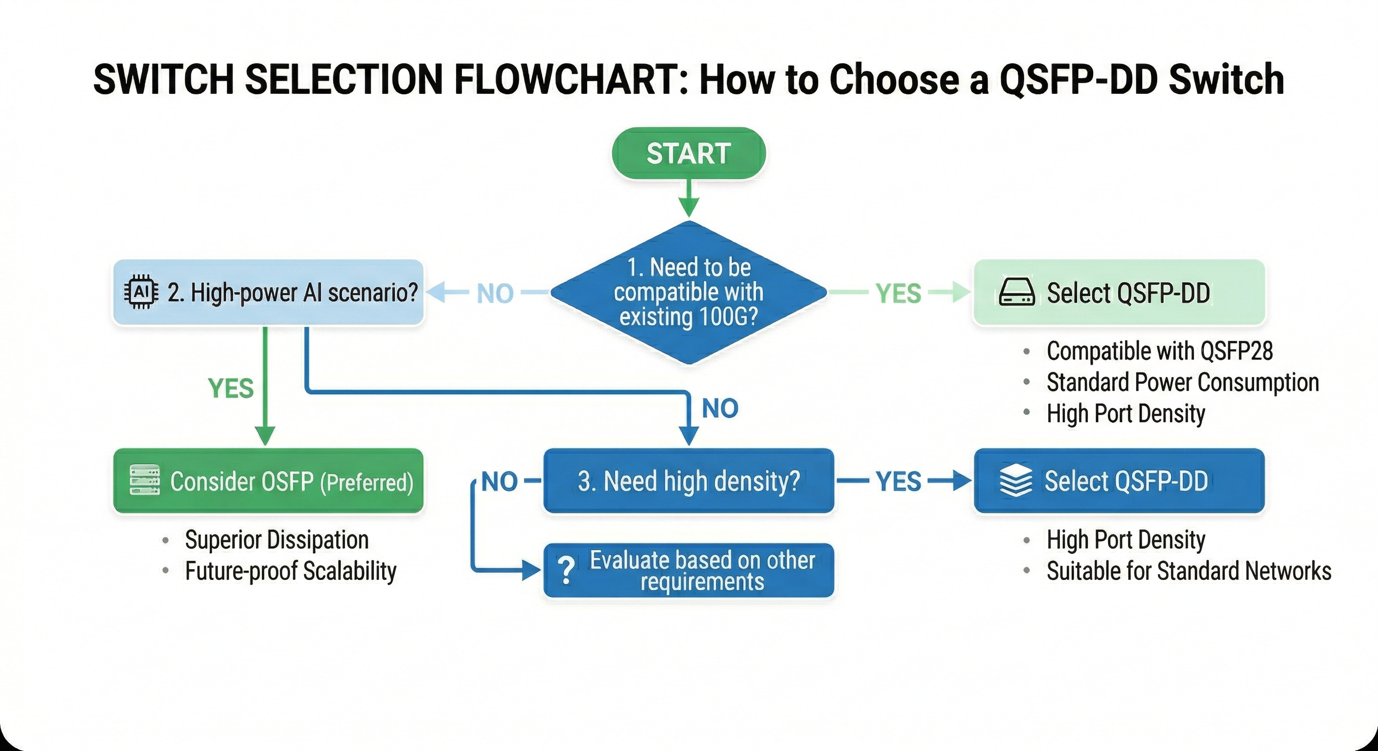
Step 1: Determine the Right Form Factor for Your Infrastructure
Before selecting reach or connector type, evaluate the form factor based on your current switches and long-term upgrade path. For 400G and 800G deployments, QSFP-DD is no longer the only option.
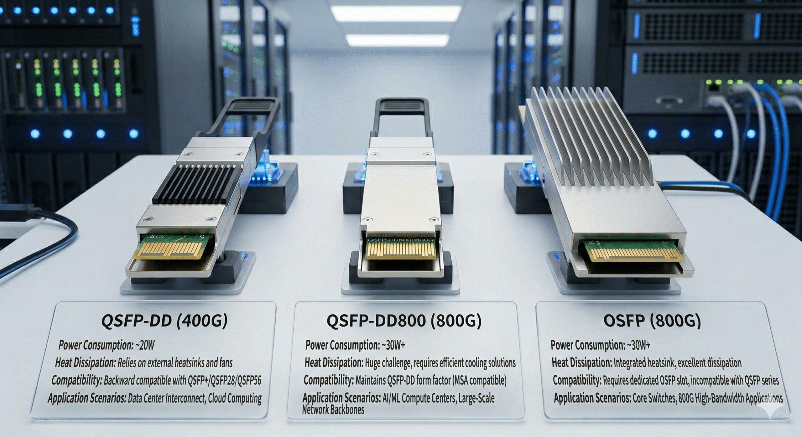
QSFP-DD vs QSFP-DD800 vs OSFP
| Form Factor |
Aggregate Rate
|
Backward Compatibility |
Best For
|
| QSFP-DD |
400G
|
QSFP+/QSFP28/QSFP56 |
Brownfield data center upgrades
|
| QSFP-DD800 |
800G
|
QSFP-DD/QSFP28 |
Phased 400G to 800G migration
|
| OSFP |
800G / 1.6T
|
Limited |
AI/HPC clusters
|
Key compatibility note: QSFP-DD and QSFP-DD800 share the same mechanical dimensions, but an 800G module will not operate at full speed in a 400G-only port (it requires host ASICs with 100G PAM4 SerDes). A 400G module can generally run at 400G speed in an 800G-capable port.
Engineering insights: Always start with your switch datasheet rather than the optical catalog. The switch ASIC ultimately determines supported form factors and speeds.
Brownfield Upgrades vs Greenfield AI Clusters
Brownfield environments typically prefer QSFP-DD because it allows reuse of existing QSFP28 optics in the new QSFP-DD cages. In contrast, new AI training clusters often choose OSFP due to its integrated heatsink, which better handles the higher thermal loads from dense GPU interconnects.
According to NVIDIA’s optical module selection guidance, OSFP is preferred for new AI clusters where cooling is the limiting factor, while QSFP-DD remains dominant in enterprise and standard cloud data centers thanks to superior backward compatibility.
Backward Compatibility Considerations
A QSFP-DD port is mechanically compatible with QSFP+ (40G), QSFP28 (100G) and QSFP56 (200G) modules. However, the QSFP-DD module cannot be placed into the legacy QSFP28 port. This one-way compatibility is partly why brownfield upgrades first deploy QSFP-DD switch cages and will eventually move to 400G/800G optics over time.
If you are comparing form factors, read our detailed QSFP-DD vs OSFP comparison to understand which standard fits your deployment.
Step 2: Select the Reach Variant Based on Distance and Fiber Plant
Once the form factor is decided, the next critical step is choosing the right reach variant. Connector mismatches remain one of the most common causes of field failures.
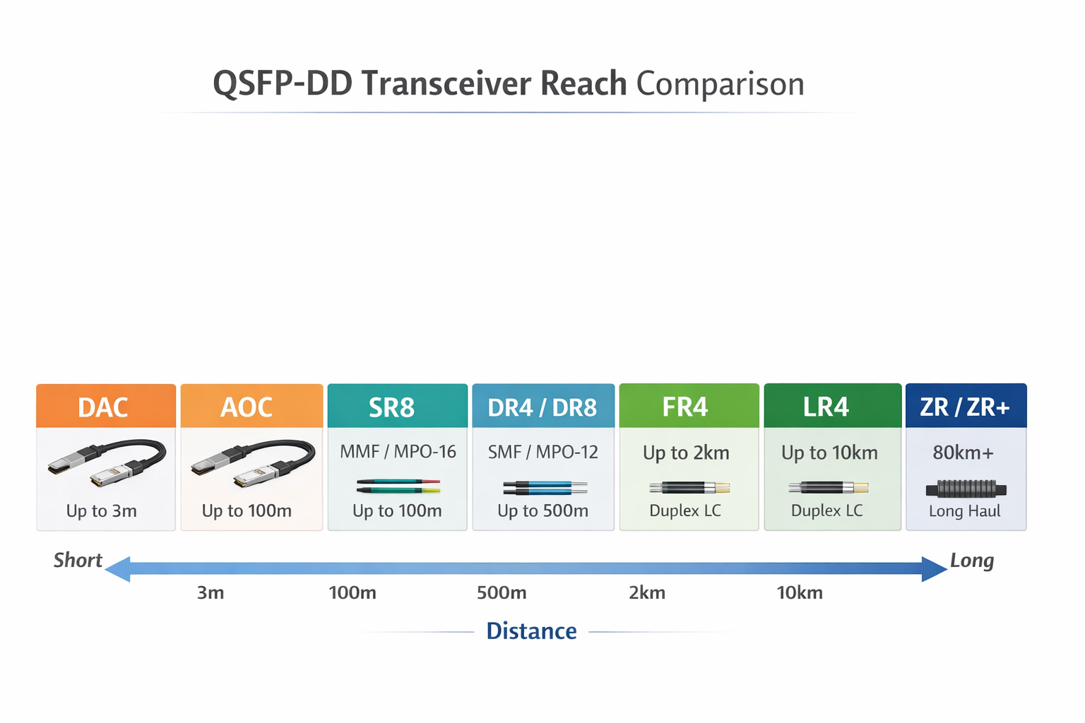
DAC and AOC (≤100 m)
Direct Attach Copper (DAC) cables support distances up to ~3 meters and offer the lowest cost, latency, and power consumption. Active Optical Cables (AOC) provide pre-terminated optical links for distances up to 100 meters.
Use DAC/AOC when:
- •Top-of-rack switch to server NIC connections are under 3 m
- •You needthe lowest possible power and latency
- •Fiber patch panels are not required
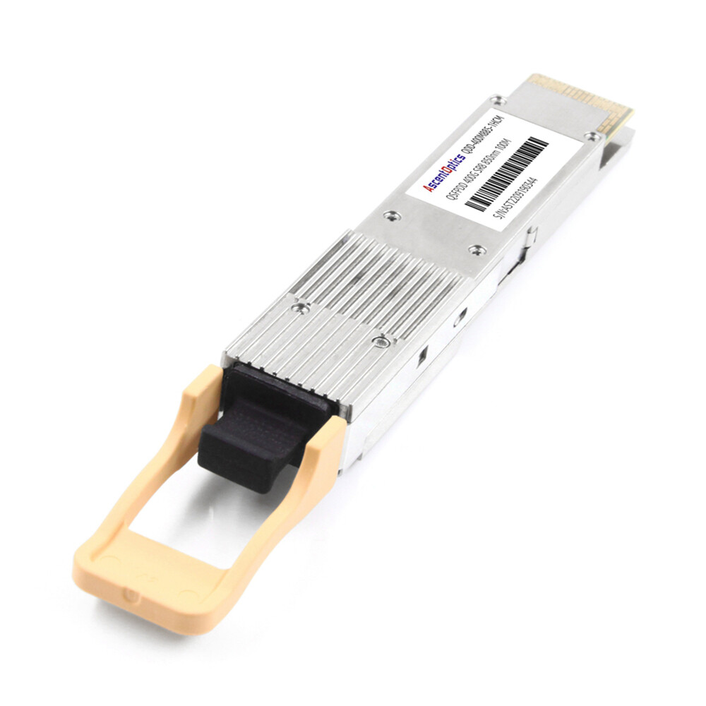
SR8 for Multimode Fiber (≤100 m)
400G/800G SR8 modules use parallel multimode fiber (OM4/OM5) and an MPO-16 connector. This is the most cost-effective choice for intra-row or adjacent-rack connections.
Use SR8 when:
- •Distance is under 100 meters
- •OM4 or OM5 multimode fiber is already installed
- •You need cost-effective short-reach 400G/800G links
DR4 / DR8 for Single-Mode Short Reach (~500 m)
DR4 (400G) and DR8 (800G) are built on single-mode fiber with an MPO-12 or MPO-16 connector for transmission up to approximately 500 meters distance. They are widely used for spine-leaf links within a pod.
Use DR4/DR8 when:
- •Distance is 100 m to 500 m
- •You need single-mode fiber for future-proofing
- •Campus or metro aggregation links are required
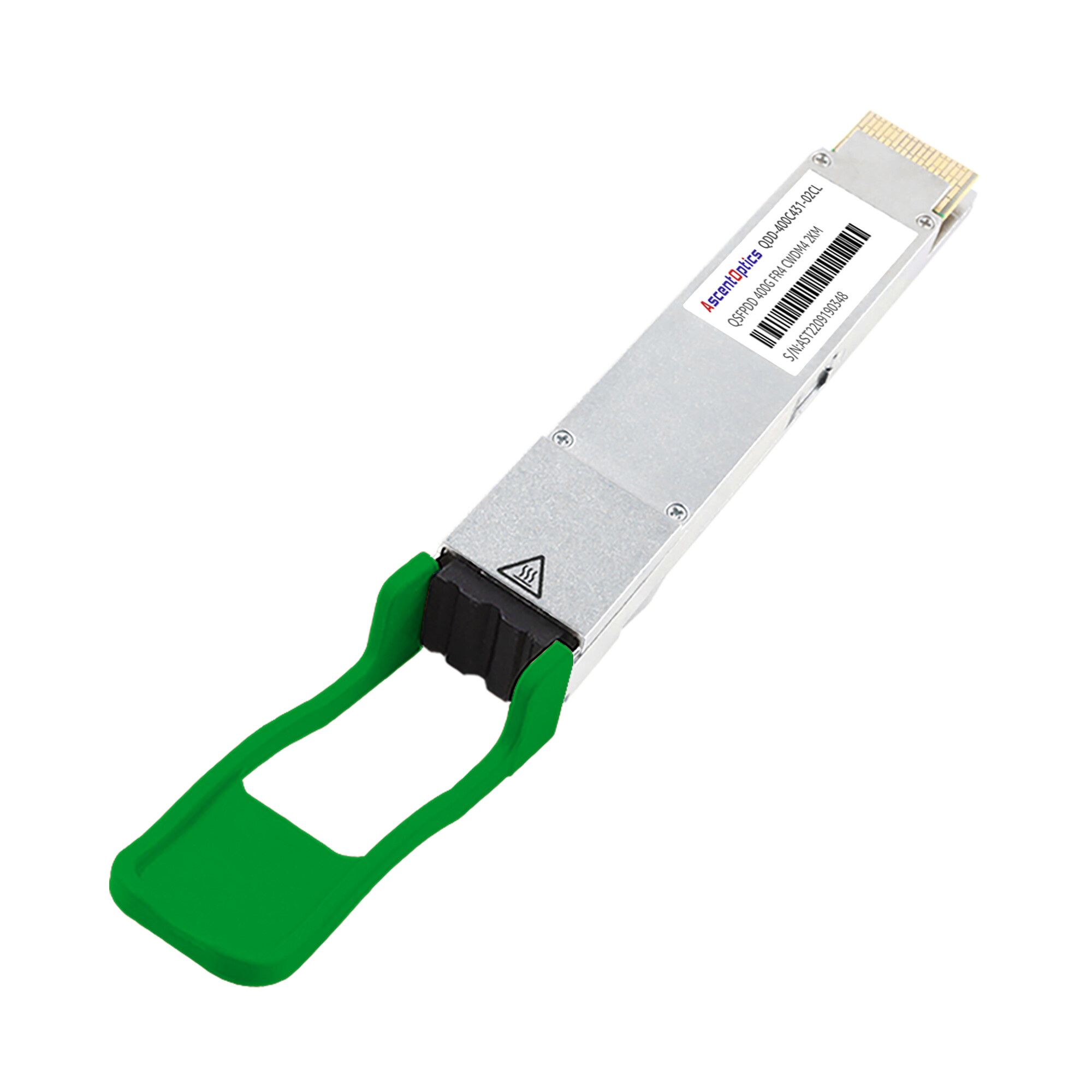
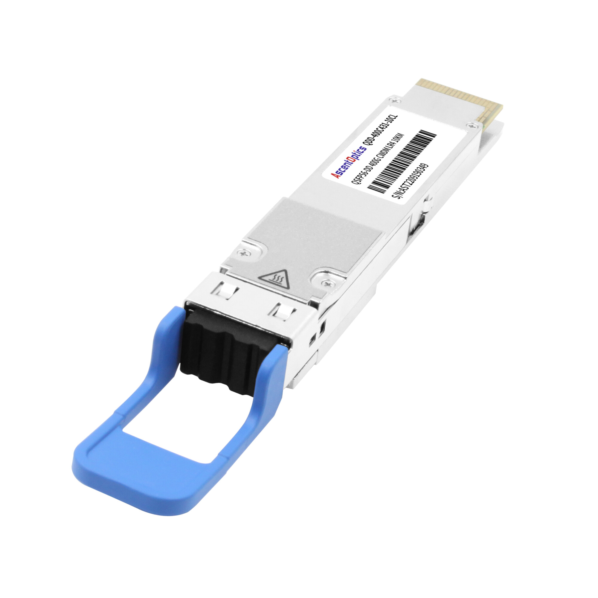
FR4 / LR4 for Metro and DCI (2 km–10 km)
FR4 and LR4 modules use duplex LC connectors and CWDM technology. LR4 extends reach to 10 km.
Use FR4/LR4 when:
- •Distance is 2 km to 10 km
- •Duplex LC connectors match your existing fiber plant
- •Data center interconnect (DCI) or campus links are needed
ZR / ZR+ for Long-Haul (80 km+)
Coherent DSP technology enables reaches of 80 km to 120 km+. These are the highest-power QSFP-DD modules, typically drawing 18–22W.
Use ZR/ZR+ when:
- •Metro or long-haul telecom backhaul is required
- •Coherent pluggable optics are specified by the network design
- •Switch ports can supply Class 8 power (15W+)
| Variant |
Distance
|
Fiber Type |
Connector |
Typical Use
|
| DAC |
≤3 m
|
Copper |
Native QSFP-DD |
Intra-rack, ToR to server
|
| AOC |
≤100 m
|
Fiber |
Native QSFP-DD |
Intra-rack / adjacent rack
|
| SR8 |
~100 m
|
OM4/OM5 MMF |
MPO-16 |
Data center short links
|
| DR4 / DR8 |
~500 m
|
SMF |
MPO-12 / MPO-16 |
Spine-leaf, campus
|
| FR4 / LR4 |
2–10 km
|
SMF |
Duplex LC |
DCI, metro edge
|
| ZR / ZR+ |
80–120+ km
|
SMF |
Duplex LC |
Telecom backhaul
|
Step 3: Choose Between DSP-Based and LPO Modules
For 800G deployments, you must decide between traditional DSP-based modules and Linear Pluggable Optics (LPO). This choice directly affects power consumption, latency, and interoperability.
When to Choose DSP-Based Transceivers
DSP-based modules include built-in digital signal processing for equalization, clock recovery, and Forward Error Correction (FEC). They offer the highest flexibility and interoperability.
Choose DSP when:
- •You operate a multi-vendor mixed environment
- •Long reach is required (FR4, LR4, ZR/ZR+)
- •You need maximum plug-and-play compatibility across different switch ASICs
When LPO Makes Sense (and When It Does Not)
LPO moves signal processing to the switch ASIC, dramatically reducing power and latency.
Choose LPO when:
- •You have a homogeneous, single-vendor switch environment
- •Latency is critical (AI/HPC, high-frequency trading)
- •Power and thermal budgets are constrained
- •Short reach only (SR8, DR8)
Important note: LPO is not yet a plug-and-play solution for most enterprise networks. Always confirm with your switch vendor whether their specific ASIC and firmware fully support LPO.
Real-world scenario: A financial services firm building a low-latency trading infrastructure chose 800G LPO modules for a homogeneous AI cluster, achieving approximately 40% power savings and more ports per rack. In their second data center with mixed switch vendors, they stayed with DSP-based modules. The dual strategy increased system complexity but delivered the right performance and cost balance for each environment.
Impact on Power, Latency, and Interoperability
| Architecture |
Power Draw |
Latency |
Interoperability |
Best Use |
| DSP-based |
~14–22W |
Higher |
Excellent |
Multi-vendor, long reach |
| LPO |
~4–12W |
Lower |
Limited |
Homogeneous, short reach |
For a deeper technical breakdown of 800G module types, see our 800G QSFP-DD module guide.
Step 4: Match Connectors and Fiber Types
Connector mismatches are expensive and surprisingly common. Before ordering any QSFP-DD module, audit your fiber plant for connector types, fiber counts, and polarity.
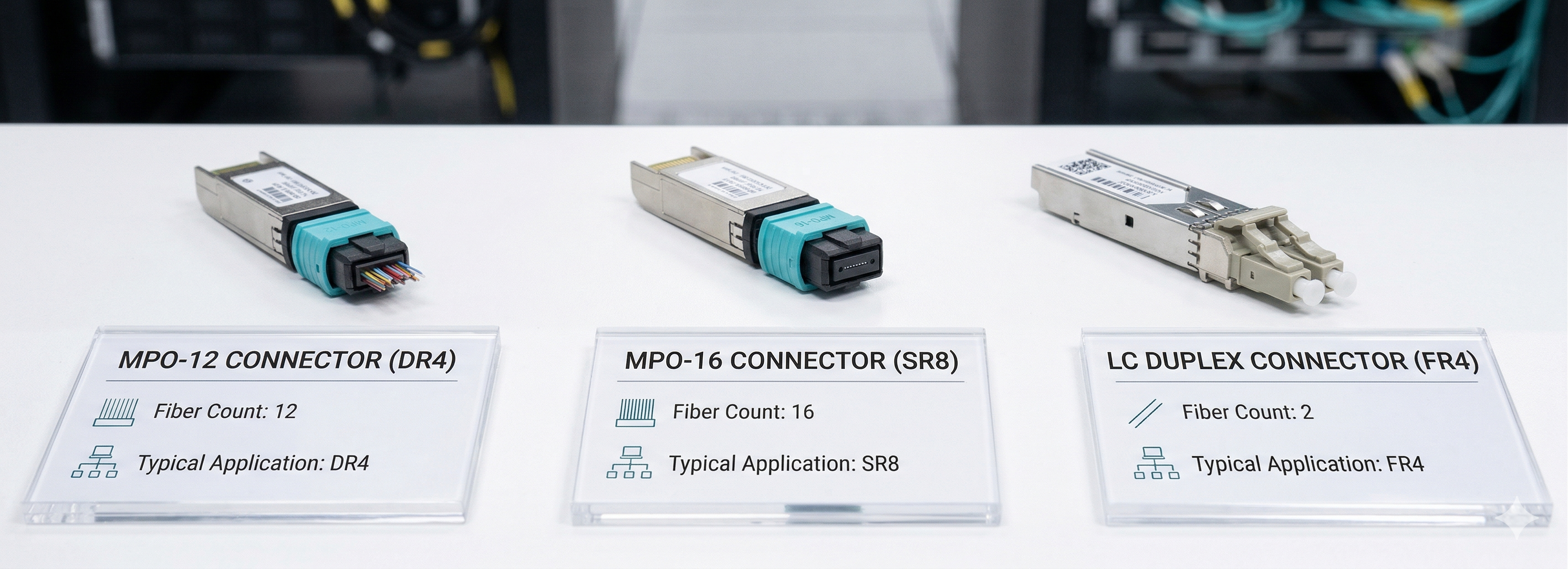
MPO-16 for Parallel Optics
SR8 and DR8 use MPO-16 connectors for 8-TX/8-RX (16-fiber) parallel transmission. Verify that your patch panels and trunk cables have the correct fiber count and polarity.
LC Duplex for CWDM Modules
FR4, LR4, and ZR/ZR+ employ duplex LC connectors to multiplex multiple lanes onto two fibers using either CWDM or coherent technology. If the fiber plant is built around LC duplex patches, these modules would fit in well.
Fiber Plant Audit Checklist
Before placing a large order, verify:
- •Connector type at both ends of the link (MPO-16, MPO-12, or LC duplex)
- •Fiber count and polarity for MPO cables
- •Fiber type (OM4/OM5 multimode vs. OS2 single-mode)
- •Cable distance with a 2–3 dB link budget margin
- •Patch panel labeling accuracy
Step 5: Validate Power Budget and Thermal Constraints
QSFP-DD modules consume far more power than 100G optics. In dense deployments, thermal design often becomes the deciding factor.
Module Power Classes Explained
QSFP-DD modules are classified by power consumption. Modern 400G/800G modules fall into Class 6 through Class 8.
| Module Class |
Power Budget
|
Typical Modules
|
| Class 6 |
Up to 10W
|
400G SR8
|
| Class 7 |
Up to 12W
|
400G FR4, DR4
|
| Class 8 |
Up to 15W+
|
400G ZR, 800G DSP
|
Always use the manufacturer’s maximum power rating (not typical) for chassis planning. A single line card fully populated with 18W ZR+ modules can generate over 500W of heat.
Calculating Total Chassis Thermal Load
To estimate total thermal load:
- Multiply max power per module by port count
- Add switch base power consumption
- Include cooling overhead (typically 30% to 50%)
Example: 32 ports × 17W 800G DSP modules = 544W. With 40% cooling overhead, the total thermal load is approximately 760W per line card.
Avoiding Hot-Spots in Dense Switches
In 1RU platforms, avoid clustering high-power modules. Spread coherent and 800G modules across the faceplate to balance heat distribution. Continuously monitor DDM/DOM temperature readings to catch thermal stress before link failures occur.
Step 6: Plan Breakout and Port Topology
Breakout cabling is one of the most cost-effective ways to integrate QSFP-DD switches with existing infrastructure. A single 400G or 800G port can support multiple lower-speed links.
Native vs Breakout Configurations
- •Native 400G/800G: Direct switch-to-switch uplinks
- •400G to 4×100G breakout: Connect 400G spine ports to 100G leaf switches
- •800G to 2×400G breakout: Bridge 800G spines to existing 400G leaf infrastructure
- •800G to 8×100G breakout: Distribute from an 800G leaf switch to multiple 100G server NICs
Common Breakout Cable Types
| Breakout Mode |
Cable Type
|
Use Case
|
| 400G → 4×100G QSFP28 |
MPO-16 to 4× MPO-12 or 4× LC duplex
|
Spine to 100G leaf
|
| 400G → 2×200G QSFP56 |
MPO-16 to 2× MPO-12
|
Spine to 200G leaf
|
| 800G → 2×400G QSFP-DD |
MPO-16 to 2× MPO-16
|
800G spine to 400G leaf
|
| 800G → 8×100G SFP28 |
MPO-16 to 8× LC duplex
|
Leaf to server NICs
|
Lab Testing Before Volume Deployment
Breakout support is vendor- and firmware-specific. Always test breakout cables with your exact switch SKU and OS version in a lab environment. Issues such as FEC mismatches or lane mapping errors can cause intermittent link flapping that is difficult to diagnose in production.
Step 7: Evaluate Vendor Compatibility and Quality
An evaluation of the provider is the last step of deciding which QSFP-DD modules to use. MSA basics are a must; differences among vendors are brought out by firmware, test measures, and support standards.
MSA Compliance and Firmware Coding
Modules must meet the QSFP-DD MSA Hardware Revision 7.0 for mechanical and electrical compatibility. The vendor must also provide firmware coding tailored to your specific OEM platform (Cisco, Arista, Juniper, NVIDIA, HPE, etc.).
DDM/DOM Monitoring Support
Digital Diagnostic Monitoring or Digital Optical Monitoring are techniques to monitor temperature, supply voltages, transmitted power, received power, and bias current of the laser inside a module. Some possible additional diagnostics are per-lane BER monitoring and advanced diagnostic capabilities in 400/800G modules.
A module without robust DDM/DOM support is a blind asset. You cannot trend performance, predict failures, or troubleshoot intermittent issues effectively. For more on this, see this DDM/DOM guide.
Third-Party Vendor Evaluation Checklist
Use this checklist to evaluate any QSFP-DD supplier:
- •MSA compliance certification for the QSFP-DD form factor
- •Firmware coding capability for your specific switch OEM
- •Platform validation reports for your exact switch model
- •Full DDM/DOM support including CMIS 4.0/5.0 where applicable
- •Thermal and power specifications with worst-case values
- •Minimum 3-year replacement warranty
- •24/7 technical support with optical networking expertise
- •Stable supply chain with inventory buffers for bulk orders
Looking for QSFP-DD transceivers with full compatibility testing and DDM support? Explore our comprehensive guide to 400G/800G QSFP-DD optical modules.
Scenario-Based QSFP-DD Selection Recommendations
The best QSFP-DD module is very dependent on the deployment scenario you would have. Here are three ordinary use instances with dedicated recommendations.
AI/ML Training Clusters
Latency and bandwidth are paramount. New installations usually favor OSFP for superior thermal performance. Where switches have already been upgraded, 800G QSFP-DD DSP modules (or LPO where the ASIC supports it) are ideal. For short intra-cluster links, use DR8 or SR8.
Enterprise Data Center Upgrades
Prioritize backward compatibility and cost control by choosing QSFP-DD to reuse existing QSFP28 optics. Use SR8 for intra-row links and FR4 for DCI. Avoid ZR/ZR+ unless metro connectivity is required. Leverage 400G-to-4×100G breakout cables to maximize the life of existing leaf switches.
Telecom and DCI Applications
Reach and reliability take precedence. Use FR4/LR4 for DCI links up to 10 km and ZR/ZR+ for metro backhaul. Confirm that switch platforms support Class 8 power. Duplex LC connectors simplify long-haul interconnections.
Pre-Purchase Checklist: Verify Before You Buy
Before placing a volume order, confirm every item on this checklist:
- •Switch ASIC + firmware compatibility confirmed for the exact module SKU
- •Form factor matches the switch cage (QSFP-DD vs QSFP-DD800 vs OSFP)
- •Reach variant aligns with actual cable distance and fiber plant
- •Connector type matches patch panel infrastructure (MPO-16, MPO-12, or LC duplex)
- •Fiber type is correct (OM4/OM5 multimode vs OS2 single-mode)
- •Power class is supported by the switch port and chassis thermal design
- •Breakout modes are tested and documented if required
- •DSP vs LPO decision is validated against switch vendor support
- •Link budget calculated with ≥2–3 dB margin for the chosen fiber and distance
- •Vendor provides MSA compliance certification, switch-specific firmware coding, and a 3-year warranty
Conclusion
As data center networks transition to 400G and 800G speeds, a systematic approach to choosing QSFP-DD transceivers is essential. Wrong selections can turn procurement into an expensive lesson and limit network scalability. By following this framework—starting with the switch, matching reach and connectors, validating power/thermal budgets, testing breakouts, and evaluating vendors—you ensure reliable, high-performance optical connectivity.
The key principles to remember:
- •Start with the switch, not the optic. The switch ASIC determines form factor and speed compatibility.
- •Match the reach variant to your actual distance and fiber plant, including connector types.
- •Validate power and thermal budgets before filling every port with high-wattage modules.
- •Test breakout configurations in a lab before production rollout.
- •Evaluate vendors on MSA compliance, firmware coding, DDM support, and platform validation.
Whether you are upgrading an enterprise data center, building an AI cluster, or expanding telecom DCI capacity, following this framework ensures your QSFP-DD selection supports reliable, high-performance optical connectivity.
Ready to source QSFP-DD transceivers for your next upgrade? Contact Shenzhen Ascent Optics engineers for a compatibility review and personalized quote.
Frequently Asked Questions (FAQs)
1. What is a QSFP-DD and why is it important?
QSFP-DD (Quad Small Form-Factor Pluggable Double Density) is a high-speed and high-density optical transceiver module designed for data centers and high-end computing environments. It supports data rates up to 400Gbps, making it critical for adequate capacity building of modern network infrastructures. Its small size and long history of it being backward compatible with the QSFP module make it a versatile choice for scalable network solutions.
2. What considerations should people have in mind when choosing QSFP-DD modules?
Buyers must evaluate data rate, transmission distance, power consumption, and compatibility with existing network equipment. Key factors include fiber type (single-mode or multimode), connector requirements, and whether the deployment needs DSP-based or LPO modules. Balancing performance, cost, and future scalability ensures optimal results.
3. What Is the Common Scenario for QTSP-DD’s Use?
QSFP-DDs are commonly used in data centers, cloud computing environments, and high performance computing networks. Common applications include data center interconnections, high-speed Ethernet, and storage area networks (SANs). Their low-latency handling of a massive amount of data is a transformer of capabilities needed for contemporary networking infrastructure.
4. Why Is Power Consumption Important for Choosing QSFP-DD?
Power consumption is an essential factor when choosing a QSFP-DD module that directly impacts the operational cost and thermal management of the network infrastructure. Modules with low power consumption translate into low energy costs and minimal heat production, ensuring their efficiency and reliability within high-density environments such as data centers.
5. How Do You Establish QSFP-DD Module Compatibility?
To ensure compatibility, the QSFP-DD module must conform to industry standards such as the MSA Multi-Source Agreement of the QSFP-DD. Also check that the module is compatible with your existing switches, routers, and other network equipment. Some manufacturers provide compatibility matrices. These matrices can be very helpful when it comes to making informed decisions.
Post Views: 1,956