Introduction
800G QSFP-DD is rapidly becoming the cornerstone optical transceiver for next-generation AI data center networks. In early 2024, one of the world’s largest hyperscale data center operators faced a critical decision. As AI training cluster architectures continued to drive explosive bandwidth demand, they needed to select 800G or higher-capacity spine switches for their next-generation infrastructure. A wrong choice could leave their existing UL-certified and mechanically validated infrastructure underutilized for up to 18 months — or worse, force a costly structural redesign and full forklift upgrade.
This challenge is faced daily by data centers worldwide as they build and scale AI systems. The 800G QSFP-DD module has emerged as a highly efficient, high-density, and backward-compatible solution, enabling a smooth transition from 400G to 800G networks.
According to industry research, demand for 800G and higher-speed optics is expected to dominate the high-speed transceiver market beyond 2026. This comprehensive guide covers everything you need to know about the 800G QSFP-DD module: what it is, how it works, and — most importantly — how to choose the right module based on your specific network requirements. Whether you are upgrading existing 400G infrastructure or building new AI training clusters from the ground up, this article provides detailed technical insights and clear selection criteria to help you make the best decision in every scenario.
Want to explore 800G optical solutions for your network? Browse our QSFP-DD transceiver portfolio.
What Is an 800G QSFP-DD Module?
This specific ‘800G QSFP-DD module’ can be termed as a transceiver which is used for 800 Gigabit Ethernet (800G) optical connections mostly in data centers, telecom, and high-speed computing environments. The module is capable of data transmission of up to 800 Giga bits per second by eight electrical lanes, where there would be 100 Gbps PAM4 signaling in each lane.
Understanding the QSFP-DD Form Factor
QSFP-DD (Quad Small Form-factor Pluggable Double Density) marks the advancement of the QSFP transceiver series. This new advancement known as “double density” in relation to the electrical design of the connectors in introduces an eight-lane electrical interface, doubling the lane count compared to traditional QSFP designs than the conventional Qsfp designs.
Key architectural specifications:
| Parameter |
Specification |
| Aggregate Data Rate |
800 Gbps (850 Gbps with FEC overhead) |
| Lane Configuration |
8 × 100G PAM4 |
| Electrical Interface |
8×100GAUI-1 or 2×400GAUI-4 |
| Modulation |
PAM4 (106.25 Gbaud per lane) |
| Power Consumption |
12W – 25W (typical) |
| Management Interface |
CMIS 5.0+ |
| Standard Compliance |
IEEE 802.3ck, QSFP-DD MSA |
QSFP-DD vs QSFP-DD800: Clarifying the Terminology
A common point of confusion involves the distinction between QSFP-DD and QSFP-DD800. These terms refer to the same physical form factor—the difference lies in the electrical signaling rate:
- •QSFP-DD (400G): Uses 8 × 50G PAM4 lanes (53.125 Gbaud)
- •QSFP-DD800 (800G): Uses 8 × 100G PAM4 lanes (106.25 Gbaud)
Both variants share identical mechanical dimensions and can physically fit into the same switch cages. However, a QSFP-DD800 module requires host ASICs capable of 100G PAM4 SerDes operation, while 400G modules operate with 50G PAM4 SerDes.
Technical Note: The QSFP-DD MSA designed the form factor to scale from 200G (8×25G) through 400G (8×50G) to 800G (8×100G) without changing physical dimensions, ensuring investment protection for data center infrastructure.
Technical Specifications and Performance
Signal Integrity and FEC Requirements
Switching from 50G to 100G PAM4 per lane signal transmission introduces significant signal integrity challenges. However, when very high data rates are considered, the impact of mild channel distortion could still end up making errors leading to network inefficiencies.
In systems operating at 800G, Forward Error Correction (FEC) becomes mandatory. The standard IEEE 802.3ck calls for a Reed-Solomon FEC which is the RS(544,514) which assigns about 30 parity symbols to each block of 514 data symbols. It delivers a coding gain of about 11.2 dB, making it possible to enables reliable transmission even over impaired links.
Power Consumption and Thermal Considerations
For 800G deployment, power consumption is an appreciable factor to consider during the design process. Conventional or standard 800G QSFP-DD module incorporating a digital signal processor (DSP) usually consumes between 14–17 watts except some long-range models that require not more than 20 watts. This is over by 30 percent to 50 percent relative to a 400G module.
| Module Generation |
Typical Power |
Thermal Load |
| 400G QSFP-DD |
10–14W |
Moderate |
| 800G QSFP-DD (DSP) |
14–17W |
High |
| 800G QSFP-DD (LPO) |
4–10W |
Low |
| 800G ZR/ZR+ |
Up to 25W+ |
Very High |
When it comes to operators who build and manage networks with thousands of ports, these otherwise benign numbers start telling a whole new story about their operations. 800G QSFP-DD module and such a well-established and conservative location of the data center with an exact number of ports equal to 1,000 may have a transceiver power demand of up to 17 kW or even more by adding the cooling load.
Planning a high-density 800G deployment? Contact our engineers for power budget analysis →
800G QSFP-DD Module Types by Distance
800G QSFP-DD modules are categorized by transmission distance and fiber type. Understanding these variants is essential for proper network design.
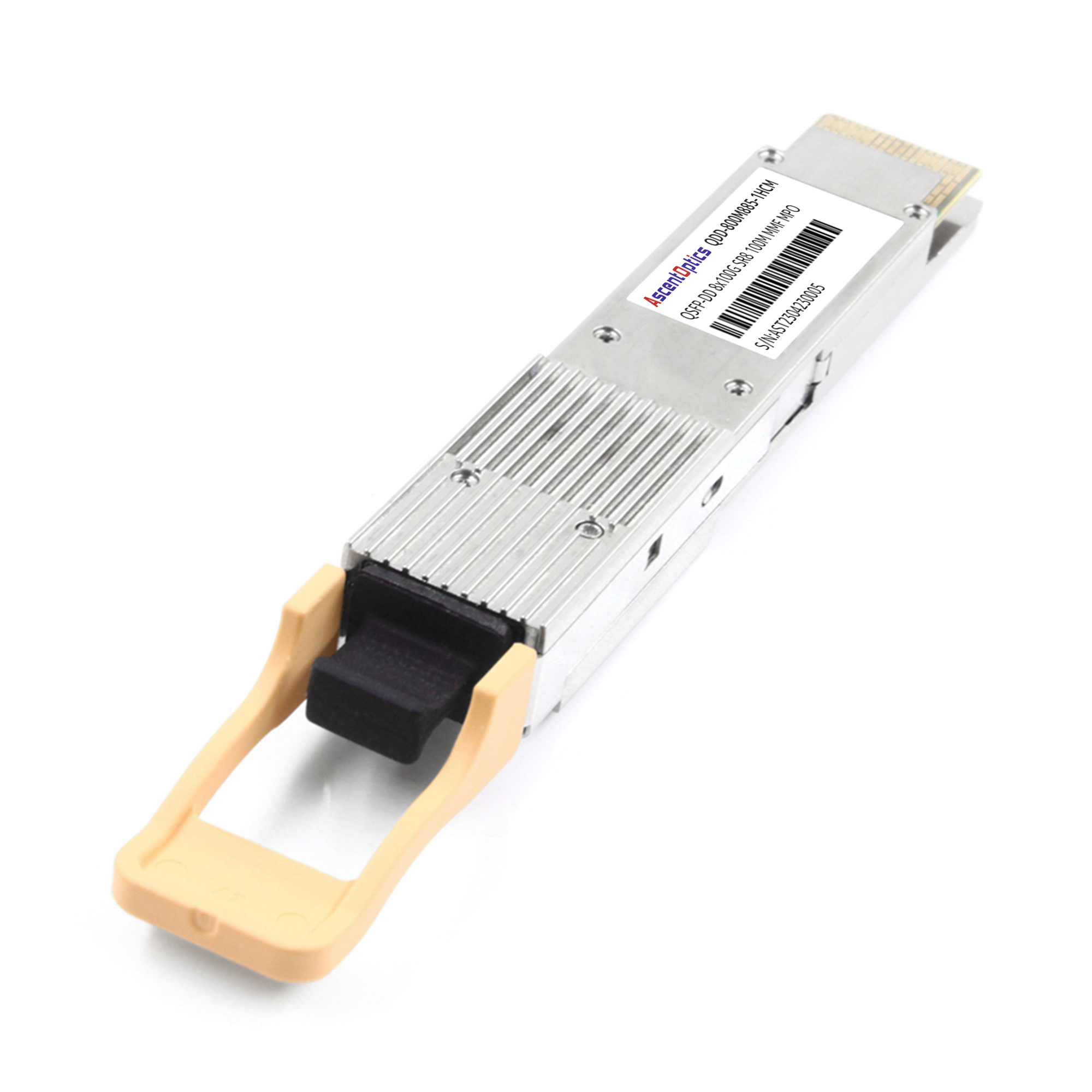
SR8 (Short Reach) – Up to 100 Meters
800GBASE-SR8 modules support distances up to 100 meters over multimode fiber (OM4/OM5). These modules use 8 parallel optical lanes at 100 Gbps each, typically with 850nm VCSEL transmitters.
key specifications:
- •Distance: 100m (OM4), 150m (OM5)
- •Fiber: Multimode (OM4/OM5)
- •Connector: MPO-16 or dual MPO-12
- •Typical use: Intra-rack connections, adjacent rack links
SR8 modules are ideal for AI clusters where GPU servers connect to top-of-rack switches within the same or adjacent racks. The short reach and lower power consumption make them cost-effective for these high-density environments.
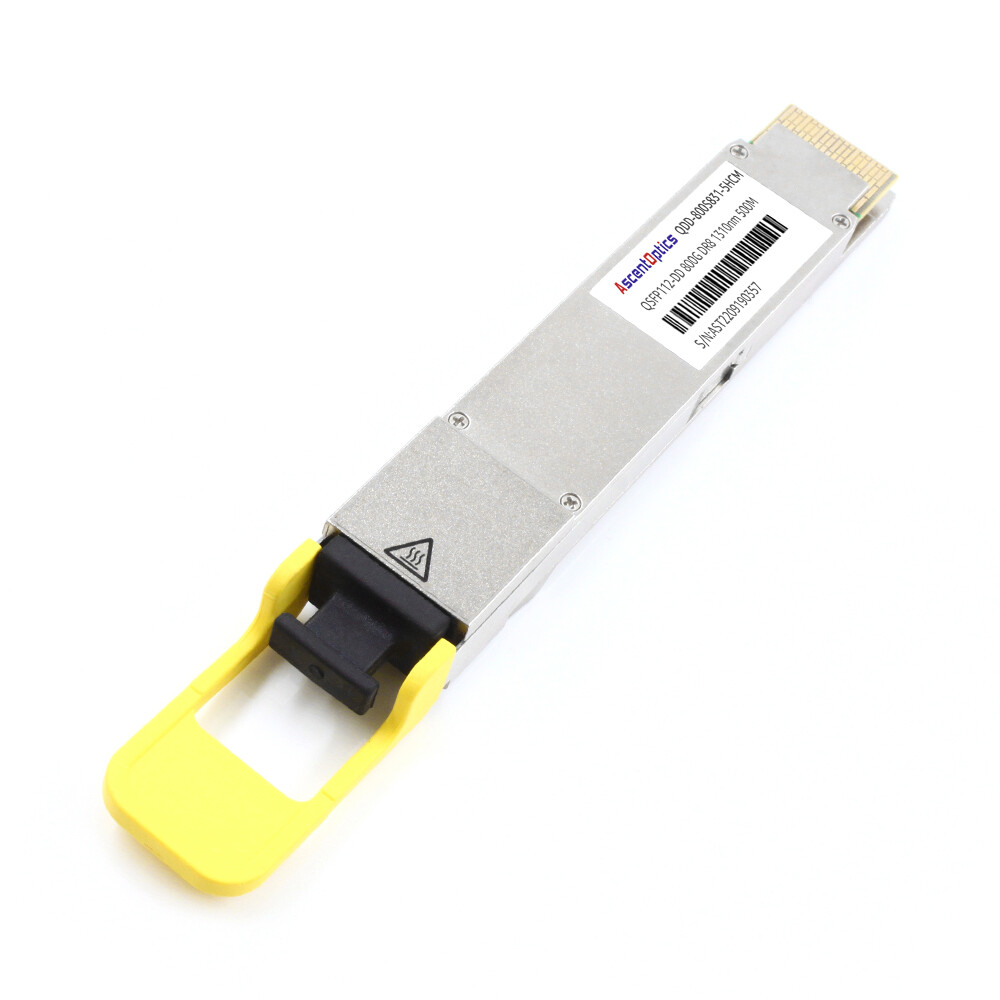
DR8 (Data Center Reach) – 500 Meters
800GBASE-DR8 modules extend reach to 500 meters over single-mode fiber using 1310nm lasers. Like SR8, DR8 uses parallel optics with 8 lanes, but the single-mode fiber enables longer distances within data center buildings.
Key specifications:
- •Distance: 500 meters
- •Fiber: Single-mode (OS2)
- •Connector: MPO-16 or dual MPO-12
- •Typical use: Spine-leaf interconnects, data center fabric
In a real-world deployment within a cloud region in Shanghai, 800G DR8 modules were used to extend connectivity between core and leaf switches. With link distances reaching up to 500 meters, the solution ensured consistent optical performance across all connections, regardless of cable routing complexity.
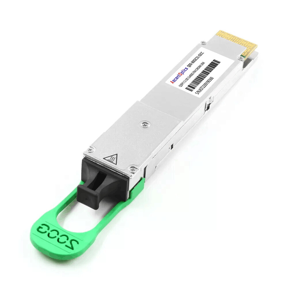
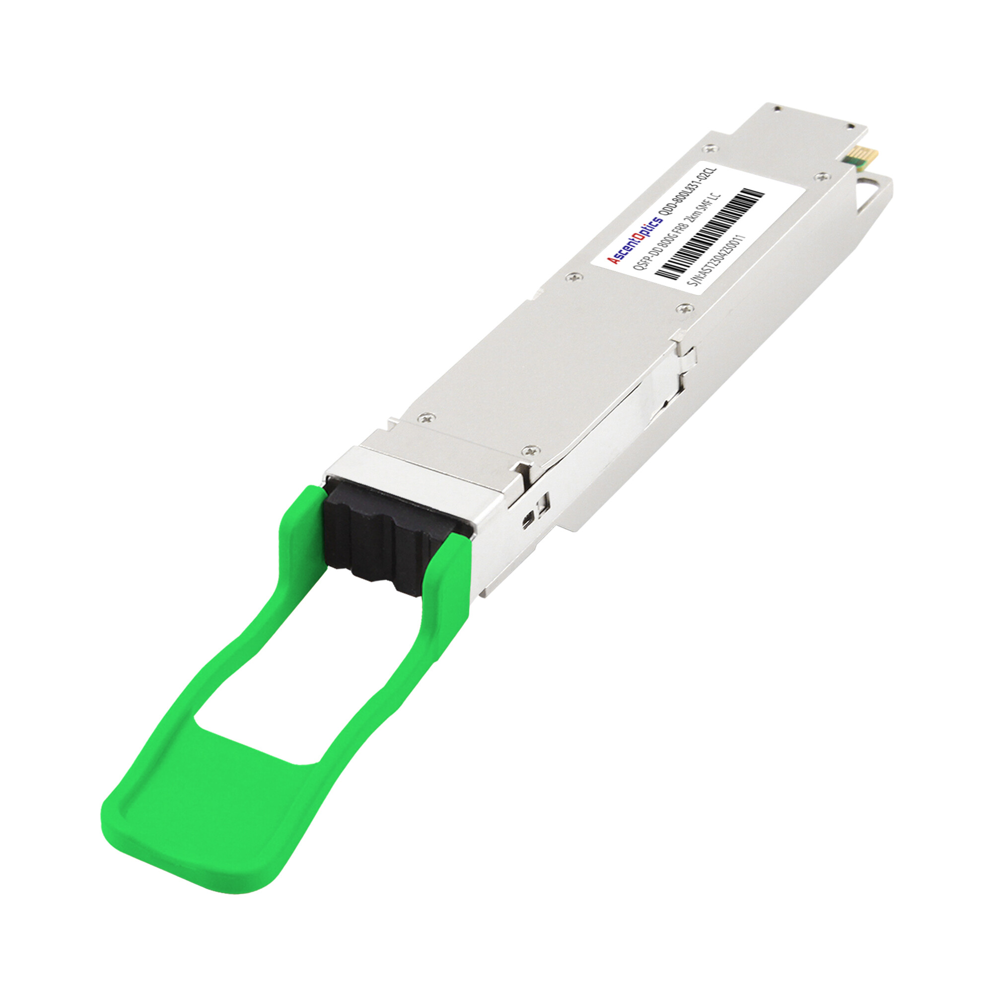
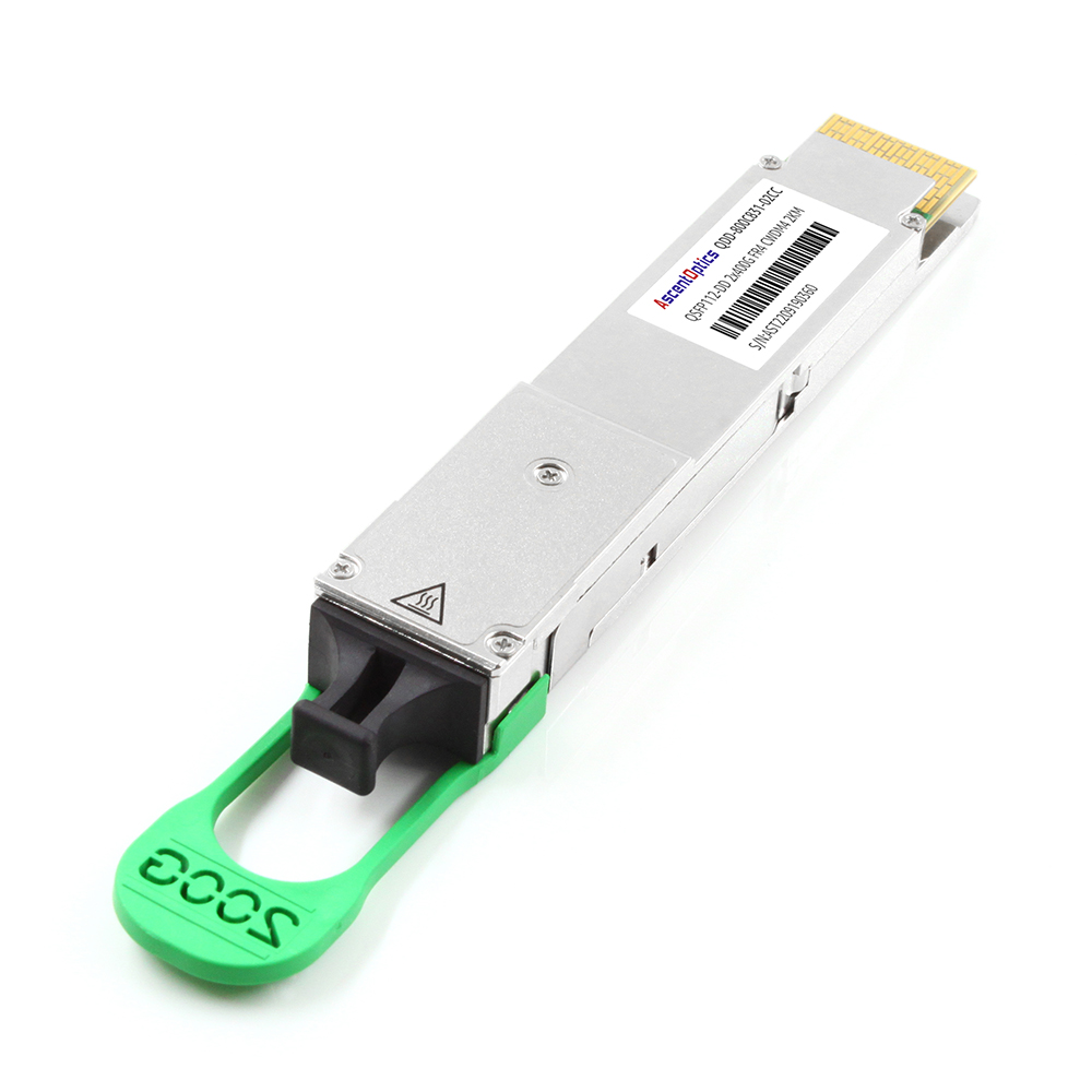
2×FR4 (Fiber Reach) – 2 Kilometers
800G-2FR4 modules take a different approach, logically splitting the 800G signal into two 400G-FR4 interfaces. Each 400G interface uses CWDM4 technology with four wavelengths multiplexed onto a single fiber pair.
Key specifications:
- •Distance: 2 kilometers
- •Fiber: Single-mode (OS2)
- •Connector: Dual LC/UPC or Dual CS/UPC
- •Typical use: Data center interconnect, campus networks
The 2×FR4 design enables breakout configurations where one 800G port connects to two separate 400G devices. This flexibility proves valuable during migration periods when networks operate with mixed 400G and 800G equipment.
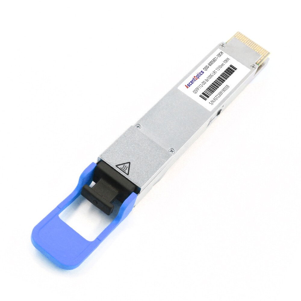
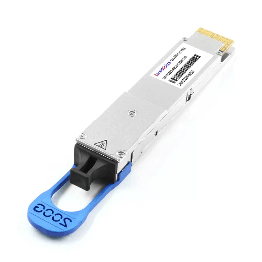
LR4 (Long Range) – 10 Kilometers
800G-2LR4 modules extend CWDM4 reach to 10 kilometers, supporting metro and regional connectivity. Like 2×FR4, these modules split the 800G signal into two 400G streams, enabling long-distance data center interconnect applications.
ZR/ZR+ (Extended Reach) – 80–120+ Kilometers
For long-haul and metro applications, 800G ZR/ZR+ modules use coherent optical technology. These modules employ advanced digital signal processing and sophisticated modulation formats to achieve extended reach.
Key specifications:
- •Distance: 80km (ZR), 120km+ (ZR+)
- •Technology: Coherent optics with DSP
- •Power: Up to 25W+
- •Typical use: Metro networks, long-haul DCI
| Module Type |
Distance |
Fiber |
Connector |
Primary Application |
| SR8 |
100m |
OM4/OM5 MMF |
MPO-16 |
Intra-rack AI clusters |
| DR8 |
500m |
OS2 SMF |
MPO-16 |
Spine-leaf fabric |
| 2×FR4 |
2km |
OS2 SMF |
Dual LC |
Data center interconnect |
| 2×LR4 |
10km |
OS2 SMF |
Dual LC |
Metro/campus networks |
| ZR/ZR+ |
80km+ |
OS2 SMF |
LC |
Long-haul transport |
800G QSFP-DD vs OSFP: Form Factor Comparison
When it comes to planning for the enhanced network designs of 800G QSFP-DD module, the transport engineers are required to select between two pluggable form factors: QSFP-DD and OSFP (Octo Small Form-factor Pluggable). The matter is made even more complicated as this choice is usually a long-term one with regards to interoperability, hardware compatibility, and extraction of heat.
Side-by-Side Technical Comparison
| Feature |
QSFP-DD800 |
OSFP-800 |
| Backward Compatibility |
Native (QSFP28/56/400G) |
Requires physical adapter |
| Thermal Capacity |
~20–25W |
~30W+ |
| Port Density |
Higher (maintains QSFP faceplate) |
Slightly lower |
| Size |
18.35mm × 89.4mm × 8.5mm |
22.5mm × 107.8mm × 13.0mm |
| Management |
CMIS 4.2/5.0 |
CMIS 4.2/5.0 |
| Best For |
Brownfield upgrades, legacy compatibility |
Greenfield AI clusters, maximum cooling |
When to Choose QSFP-DD800
QSFP-DD800 is the optimal choice when:
- •Preserving existing infrastructure: The backward compatibility with QSFP28, QSFP56, and 400G QSFP-DD modules protects existing switch investments.
- •Maximizing port density: The compact form factor enables more ports per rack unit, critical for space-constrained facilities.
- •Brownfield migrations: Organizations upgrading from 100G/400G can deploy QSFP-DD800 in existing QSFP-DD cages without hardware changes.
When to Choose OSFP
OSFP is the optimal choice when:
- •Building new AI clusters: The larger thermal capacity (30W+) accommodates high-power coherent optics and future 1.6T modules.
- •Maximum cooling required: The integrated heatsink design provides superior thermal dissipation for dense deployments.
- •Future-proofing priority: OSFP is positioned as the primary form factor for 1.6T and beyond.
Interoperability Considerations
It is important to note that while a QSFP-DD module and an OSFP module can’t really fit into one another, they do support operation on the same optical link. For instance, the 800G QSFP-DD module on one end can connect to the OSFP-800 FR4 module on the other end through a link, as long as their optical parameters are the same at both ends.
Engineering Insight: Many hyperscale operators standardize on OSFP for new AI-focused data centers while maintaining QSFP-DD for general-purpose compute facilities, creating a mixed environment that requires careful inventory management.
LPO vs DSP-Based 800G Transceivers
The introduction of 800G networking introduces a key decision point between adopting DSP-based transceivers, as in the past, or following a newer approach of Linear Pluggable Optics (LPO). The decision has implications for energy usage, signal delay, and interoperability.
Linear Pluggable Optics (LPO)
LPO modules eliminate the DSP chip from the transceiver, instead relying on the host switch ASIC to perform signal processing. This architectural change yields significant benefits:
Advantages:
- •Lower power consumption: 4–10W vs. 14–17W for DSP-based modules
- •Reduced latency: Eliminates DSP processing delays (approximately 50–100ns savings)
- •Lower cost: Fewer components reduce manufacturing costs
- •Simplified thermal design: Less heat generation simplifies cooling
Requirements:
- •Host ASIC must support signal retiming and equalization
- •CMIS 5.0 management interface with proper lane mapping
Potentially reduced interoperability with mixed vendor environments
DSP-Based Transceivers
Traditional DSP-based modules include on-board digital signal processors that handle signal conditioning, equalization, and error correction.
Advantages:
- •Broad interoperability: DSP compensation enables operation across diverse host platforms
- •Vendor flexibility: Easier to mix and match switch and transceiver vendors
- •Proven reliability: Established technology with extensive deployment history
- •Longer reach support: DSP enables extended-reach variants (LR4, ZR)
Trade-offs:
- •Higher power consumption
- •Slightly increased latency
- •Higher per-port costs
Selection Guidance
| Factor |
Choose LPO If |
Choose DSP If |
| Application |
AI/HPC clusters, latency-sensitive |
General data center, long reach |
| Power budget |
Constrained thermal environment |
Adequate cooling capacity |
| Interoperability |
Single-vendor homogeneous environment |
Multi-vendor mixed environment |
| Host platform |
Modern ASIC with LPO support |
Legacy or mixed ASIC platforms |
| Reach requirements |
SR8, DR8 (short/medium) |
LR4, ZR (long distance) |
Maria Gonzalez works as a manager in a financial services company where her team had reasons to look at the use of the 800G QSFP-DD module but only for latency benefits for their high-frequency trading system infrastructure. For saving 100 nanoseconds per hop extrapolated to thousands of transactions a day, the payoff was worth the efficiency.
Interested in LPO 800G modules for your AI cluster? Explore our LPO QSFP-DD800 product line →
Applications and Use Cases
800G QSFP-DD modules serve diverse applications across modern networking infrastructure.
AI/ML Training Clusters
AI infrastructure represents the primary growth driver for 800G optics. Large language model training requires massive GPU clusters with high-bandwidth, low-latency interconnects.
Key requirements:
- •High bandwidth density (800G per port)
- •Low latency for GPU synchronization
- •Low power consumption (favoring LPO where possible)
- •SR8 for intra-rack, DR8 for spine-leaf
The ratio of optical transceivers to AI accelerator chips has increased from approximately 1:3 in traditional compute environments to 1:4.5 or even 1:8 in large training clusters, significantly increasing optical module demand.
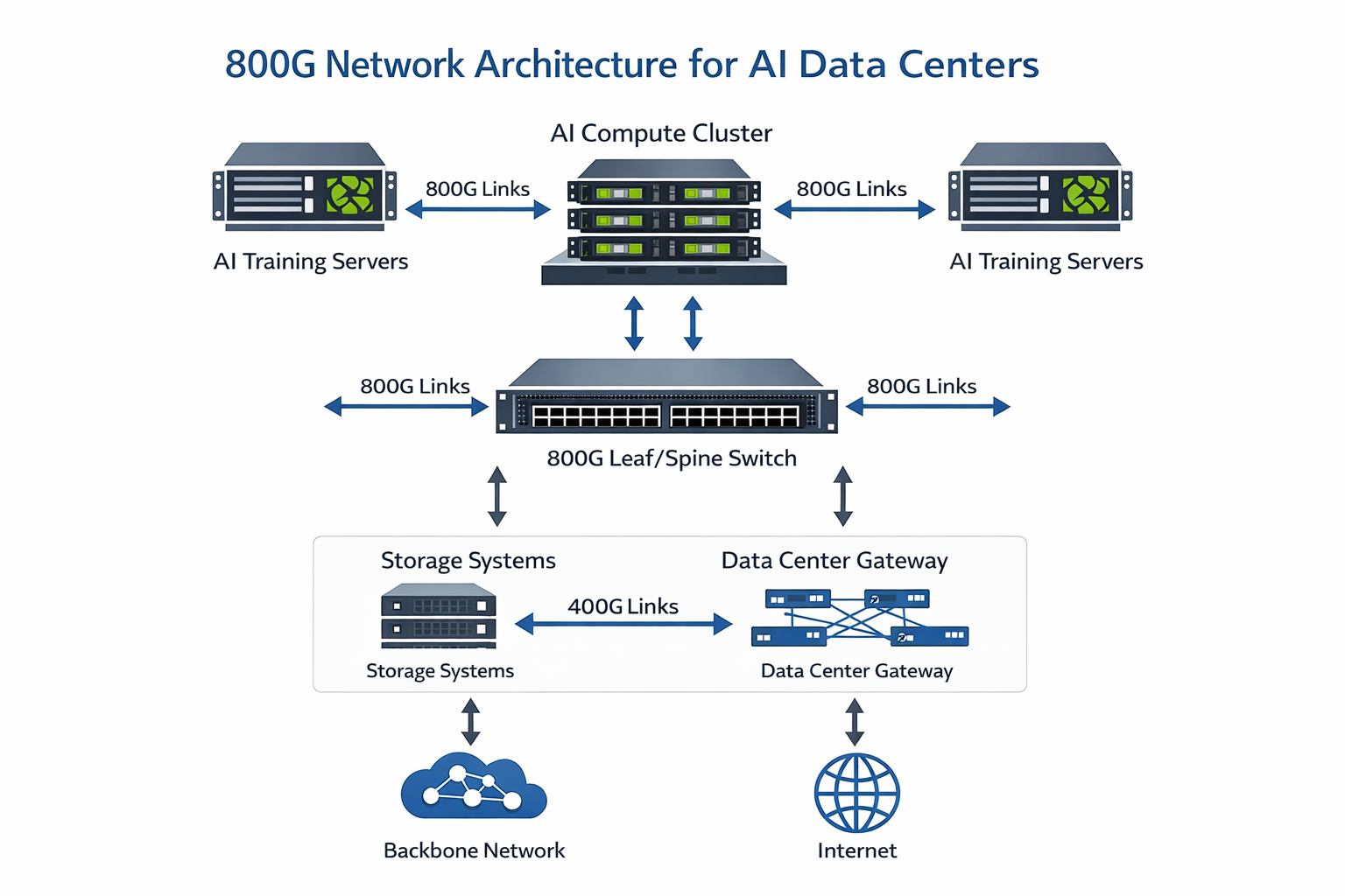
Hyperscale Data Center Fabrics
Cloud providers deploy 800G for spine-leaf and fabric interconnects, enabling higher bandwidth without increasing switch port counts.
Deployment patterns:
- •800G spine switches with 400G leaf downlinks
- •800G leaf switches with 100G/200G server connections
- •2×FR4 modules for DCI between availability zones
High-Performance Computing (HPC)
Supercomputing fabrics use 800G in InfiniBand NDR (Next Data Rate) connections. Because InfiniBand technology inherently supports the 800G transmission rate in its roadmap, it can be easily adopted in HPC network fabrics.
Telecommunications and Metro Networks
800G ZR/ZR+ coherent modules enable high-capacity transport for:
- •5G backhaul and midhaul networks
- •Metro aggregation networks
- •Long-haul data center interconnect
How to Choose the Right 800G QSFP-DD Module
Selecting the appropriate 800G QSFP-DD module requires systematic evaluation of multiple technical factors.
Step 1: Determine Form Factor Compatibility
Assess your existing infrastructure:
- •Existing QSFP-DD switches: Choose QSFP-DD800 for backward compatibility
- •New AI-focused deployment: Consider OSFP for maximum thermal headroom
- •Mixed environment: Standardize on one form factor per facility where possible
Step 2: Define Reach Requirements
Map your physical connectivity needs:
- •Intra-rack: SR8 (up to 100m) with multimode fiber
- •Within data hall: DR8 (500m) with single-mode fiber
- •Campus/DCI: 2×FR4 (2km) or 2×LR4 (10km)
- •Metro/Long-haul: ZR/ZR+ coherent modules
Step 3: Evaluate Power and Thermal Constraints
Calculate total power budget:
- •Multiply per-module power by port count
- •Add headroom for thermal throttling scenarios
- •Consider LPO for power-constrained environments
Example calculation:
- •32-port 800G line card
- •17W per DSP-based module
- •Total: 544W per line card
- •With cooling overhead: ~750W thermal load per card
Step 4: Assess Breakout Requirements
Determine if you need breakout configurations:
- •Native 800G: Direct 800G switch-to-switch links
- •2×400G breakout: Connect to existing 400G equipment
- •8×100G breakout: Distribute to server NICs
Step 5: Select LPO vs DSP
Choose based on your environment:
- •LPO: Single-vendor AI clusters, latency-critical applications, power-constrained deployments
- •DSP: Multi-vendor environments, long-reach requirements, maximum interoperability
Pre-Purchase Verification Checklist
Before committing to large-scale procurement:
- •Verify switch ASIC compatibility with target module type
- •Confirm CMIS 5.0 support for management and telemetry
- •Validate fiber infrastructure (type, distance, connector compatibility)
- •Calculate total rack-level power and thermal capacity
- •Test interoperability in lab environment with actual hardware
- •Verify FEC requirements and host-side configuration
- •Review breakout cable availability and compatibility
- •Confirm warranty and MTBF specifications with vendor
Deployment Considerations
Power and Thermal Planning
800G deployments require careful thermal management. High-density 32-port line cards with 800G modules can generate over 500W of transceiver heat alone.
Best practices:
- •Use switches with adequate thermal design for 20W+ per port
- •Ensure front-to-back or back-to-front airflow alignment
- •Consider liquid cooling for ultra-dense AI clusters
- •Monitor thermal throttling alerts via CMIS telemetry
Interoperability Testing
Before network-wide deployment:
1.Lab validation: Test modules with your specific switch ASICs
2.BER testing: Verify bit error rates meet specifications
3. FEC margin testing: Confirm adequate FEC headroom
4. Breakout validation: Test all lane mapping configurations
5. Thermal stress testing: Validate operation at maximum temperature
Fiber Infrastructure Assessment
Ensure your fiber plant supports 800G requirements:
- •Multimode: Verify OM4 or OM5 for SR8 applications
- •Single-mode: OS2 required for DR8 and longer reach
- •Connectors: Confirm MPO-16, dual MPO-12, or LC availability
- •Cleaning: Implement proper fiber cleaning procedures for MPO connectors
2025 Market Context and Future Outlook
Adoption Timeline
The 800G optical market is experiencing rapid acceleration:
- •2024: 800G entered large-scale commercial deployment
- •2025: 800G becomes mainstream for new data center builds
- •2026: 800G+ optics projected to exceed 60% of high-speed module shipments
- •2026–2027: Co-packaged optics (CPO) enters volume deployment
- •2027+: 1.6T modules become widely available
Market Growth Metrics
Industry analysts project significant growth:
- •Global optical transceiver market: $12.73 billion in 2025(60% year-over-year growth)
- •Unit demand: Goldman Sachs raised 2026 forecast to 5 million units(58% increase)
- •Market share: 800G+ modules growing from 19.5% (2024) to 60%+ (2026)
Technology Evolution
Emerging trends:
- •Silicon photonics: Enabling lower power and cost at scale
- •Co-packaged optics (CPO): Integrating optics with switch ASICs
- •Linear drive pluggable (LPO): Reducing power and latency
- •6T development: Next generation using 200G PAM4 per lane
Conclusion
Aiding in the development of next-generation data centers, artificial intelligence (AI) infrastructure, and high-performance networks are 800G QSFP-DD modules. Moving from 400G to 800G, the bandwidth capacity is increased twofold while the port density remains unchanged, thus responding to the pressure of rapidly increasing data flow.
Key takeaways:
- •QSFP-DD800 provides backward compatibility with existing QSFP infrastructure while delivering 800G performance
- •Module selection depends on reach requirements (SR8, DR8, FR4, LR4), power constraints, and breakout needs
- •LPO technology offers significant power and latency advantages for AI clusters with compatible host platforms
- •Form factor choice between QSFP-DD and OSFP should consider existing infrastructure, thermal requirements, and future roadmap
- •Thorough testing is essential before large-scale deployment to ensure interoperability and performance
In light of the increasing demands on network bandwidth caused by AI workload, the 800G QSFP-DD modules will usher in the era of high-speed communication connectivity. Those businesses intending to upgrade their infrastructure should consider which option would best suit them using the decision framework outlined in this guide.
Ready to deploy 800G connectivity in your network? Contact Ascent Optics for expert guidance on module selection, compatibility verification, and deployment planning. Our engineering team can help you navigate the transition to 800G with confidence.
Frequently Asked Questions
1. What is the difference between QSFP-DD and QSFP-DD800?
QSFP-DD refers to the physical form factor, while QSFP-DD800 specifically indicates 800G capability using 8×100G PAM4 lanes. Both share the same mechanical dimensions, but QSFP-DD800 requires 100G PAM4 SerDes support from host ASICs.
2. Can I use 800G modules in 400G QSFP-DD ports?
No. While 400G modules can work in 800G-capable ports (at 400G speeds), 800G modules require host ASICs with 100G PAM4 SerDes capability that 400G switches do not have.
3. What is the maximum power consumption of 800G QSFP-DD modules?
Standard DSP-based modules consume 14–17W, while LPO variants use 4–10W. Extended-reach coherent modules (ZR/ZR+) can require 20–25W.
4. Which is better for AI clusters: QSFP-DD or OSFP?
OSFP is often preferred for new AI clusters due to superior thermal capacity (30W+), while QSFP-DD800 is ideal for facilities with existing QSFP infrastructure that need backward compatibility.
5. What fiber type do I need for 800G?
SR8 modules use OM4/OM5 multimode fiber, while all other types (DR8, FR4, LR4, ZR) require OS2 single-mode fiber.
6. Can QSFP-DD and OSFP modules communicate with each other?
Yes, on the optical layer. A QSFP-DD800 2×FR4 can interoperate with an OSFP-800 2×FR4, provided both use the same optical specifications (wavelengths, power levels).
Internal Links to Add:
- •QSFP-DD product portfolio page
- •400G vs 800G comparison article (if exists)
- •LPO QSFP-DD800 product pages (SR8, DR8)
- •Contact/engineering consultation page
External Authority Links:
- •QSFP-DD MSA specifications
- •IEEE 802.3ck standard
- •TrendForce market research
- •Goldman Sachs optical module forecast
Post Views: 2,941