With respect to cabling infrastructure, a poor investment decision can easily exceed $50,000. Choosing the wrong 400G transceiver module can significantly impact data center performance, leading to insufficient bandwidth or unnecessarily high power consumption.
Many early adopters of 400G QSFP-DD faced similar challenges—just as the industry did during the transition to 10G a decade ago. In many cases, organizations selected modules based only on reach requirements, leaving future scalability and compatibility to chance.
This time, such trial-and-error approaches are no longer acceptable.
The four mainstream 400G QSFP-DD transceiver Types—SR8, DR4, FR4, and LR4—are designed for different transmission distances, fiber types, and power requirements. Choosing the wrong option can lead to higher costs, inefficient upgrades, and limited scalability toward 800G.
A structured decision framework is essential when selecting 400G optics for applications ranging from AI clusters to data center interconnect (DCI).
What Is QSFP-DD? Understanding the 400G Foundation
Before comparing transceiver types, it is important to understand why QSFP-DD exists and how it differs from earlier form factors.
QSFP-DD Double Density Architecture
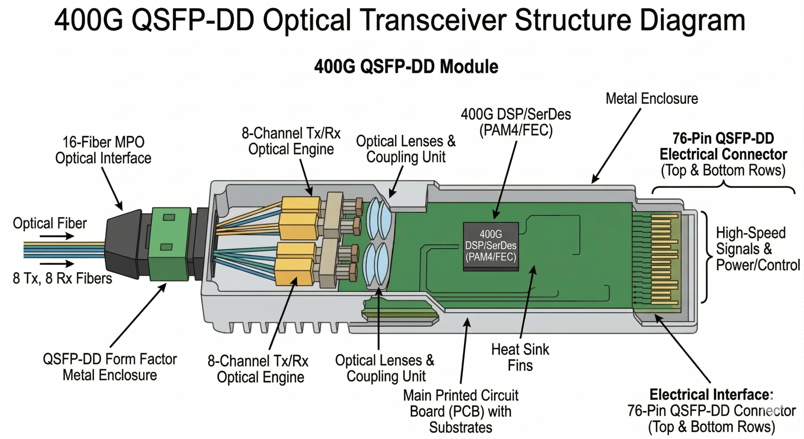
QSFP-DD (Quad Small Form-factor Pluggable Double Density) increases the number of electrical lanes from 4 (in QSFP28) to 8, enabling higher bandwidth within the same physical footprint. It uses 8 × 50 Gbps PAM4 electrical lanes to achieve an aggregate bandwidth of 400 Gbps.
Key architectural advantages:
- •8 electrical lanes: 8 × 50G PAM4 electrical interface (400GAUI-8)
- •Backward compatibility: supports QSFP28, QSFP+, and QSFP
- •Same port footprint: 4× bandwidth without increasing switch faceplate size
- •800G roadmap: QSFP-DD800 supports 8 × 100G for future 800G deployments
PAM4 is a method of Pulse Amplitude Modulation using four levels. Unlike NRZ, where one bit is transmitted per symbol, PAM4 uses two bits per symbol (“00,” “01,” “10,” “11”). Thus, the data rate is essentially doubled without increasing the baud rate, although higher DSP and stronger FEC are required.
400G QSFP-DD vs QSFP28: When to Upgrade
If you are currently using 100G QSFP28, upgrading to 400G QSFP-DD involves more than just increasing speed—it requires system-level considerations such as power, cooling, and cabling.
| Parameter |
QSFP28 (100G) |
QSFP-DD (400G) |
| Electrical Lanes |
4 × 25G NRZ |
8 × 50G PAM4 |
| Aggregate Bandwidth |
100 Gbps |
400 Gbps |
| Power Consumption |
3.5–4.5W |
10–15W |
| Thermal Design |
Standard |
High-density cooling required |
| Breakout Support |
100G → 4×25G |
400G → 4×100G |
When to stay with QSFP28:
- •Existing 100G infrastructure meets current and 24-month bandwidth needs
- •Power or cooling constraints limit thermal headroom
- •Cost optimization outweighs bandwidth scaling requirements
When to deploy QSFP-DD:
- •AI/ML workloads require maximum bandwidth density
- •Hyperscale spine-leaf architectures demand 400G+ per port
- •Planning 800G migration path within 3–5 years
- •New data center build with modern thermal design
Real-World Example
During a recent infrastructure upgrade, Marcus Chen, a senior networking architect at an AI startup in Seattle, needed to connect 512 H100 GPUs across 16 racks. Initially, the team planned to stay with 100G QSFP28 modules purely for cost reasons. However, after calculating the cabling impact—four times the fiber links, four times the optical modules, and four times the cable runs—Marcus realized that moving to 400G QSFP-DD (SR8, DR4, and FR4) would actually simplify the overall topology, reduce long-term complexity, and deliver better performance per port. This insight led to a complete redesign of their network architecture.
Explore Ascent Optics’ 400G QSFP-DD transceiver portfolio →
400G QSFP-DD Transceiver Types: Complete Comparison
Now let’s examine the four main 400G QSFP-DD transceiver types, their specifications, and ideal use cases.
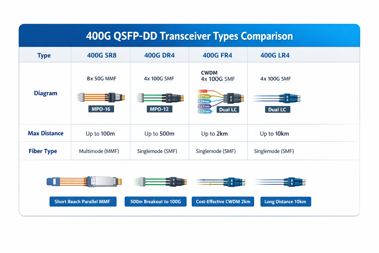
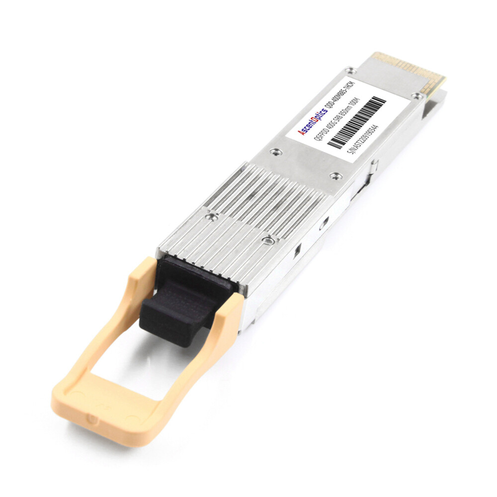
400G SR8: Short Reach Multimode
Specifications:
- •Maximum distance: 70m (OM3), 100m (OM4)
- •Fiber type: Multimode fiber (MMF)
- •Connector: MPO-16 (16-fiber)
- •Wavelength: 850nm (VCSEL)
- •Power consumption: 6–8W
- •Standard: IEEE 802.3cm
The 400G QSFP-DD SR8 uses parallel multimode optics with 8 transmit and 8 receive lanes, each operating at 50 Gbps PAM4. It requires 16 fibers total—hence the MPO-16 connector.
Best for:
- •In-rack switch-to-server connections
- •Top-of-Rack (ToR) to server links under 100m
- •High-density data centers with existing multimode fiber infrastructure
- •Lowest-power 400G option for short distances
Key considerations:
SR8 requires multimode fiber (typically OM3 or OM4) with an MPO-16 connector. It is not compatible with single-mode fiber deployments.
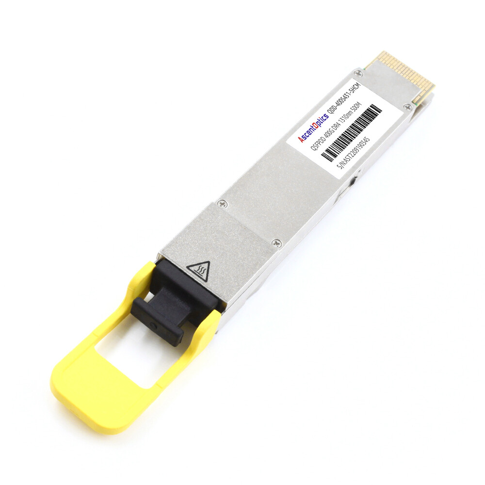
400G DR4: Direct Reach Single-Mode
Specifications:
- •Maximum distance: 500m
- •Fiber type: Single-mode fiber (SMF)
- •Connector: MPO-12 APC (8 fibers)
- •Wavelength: 1310nm (parallel optics)
- •Power consumption: 8–10W
- •Standard: IEEE 802.3bs
The 400G DR4 uses 4 parallel lanes, with each optical lane operating at 100 Gbps PAM4. This results in an 8-fiber implementation (4 TX + 4 RX), using a standard MPO-12 connector with 4 empty fiber spots.
Best for:
- •Data center spine-leaf architectures
- •ToR-to-spine links under 500m
- •Facilities with existing MPO-12 single-mode infrastructure
- •Cost-effective single-mode deployment
DR4 breakout capability:
DR4 supports 400G → 4×100G breakout using appropriate fiber patch cords. A single 400G DR4 port can connect to four 100G QSFP28 DR1 modules, enabling seamless integration with existing 100G endpoints during phased upgrades.
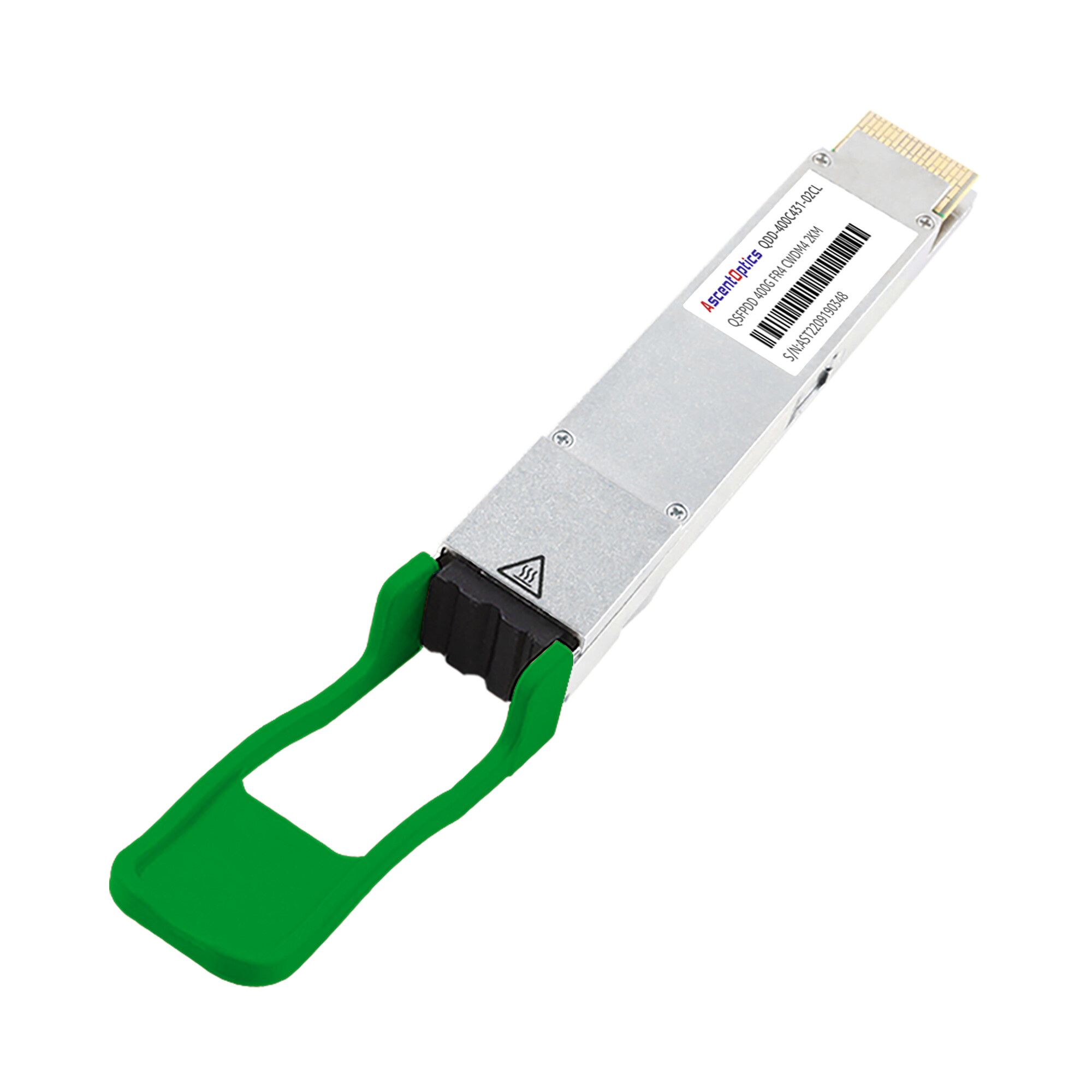
400G FR4: Fiber Reach (AI Cluster Favorite)
Specifications:
- •Maximum distance: 2km
- •Fiber type: Single-mode fiber (SMF)
- •Connector: Duplex LC
- •Wavelengths: 1271nm, 1291nm, 1311nm, 1331nm (CWDM4)
- •Power consumption: 8–12W (QSFP112: ≤9W)
- •Standard: IEEE 802.3cu, 100G Lambda MSA
The 400G FR4 uses coarse wavelength division multiplexing (CWDM4) to transmit four 100Gbps channels over a single fiber pair. Internal gearboxing merges 8 electrical lanes into 4 optical lanes.
Why FR4 dominates AI clusters:
When AWS, Meta, and Google deploy AI training infrastructure, they overwhelmingly select FR4 for links under 2km. The reasons are compelling:
- •Optimal cost-performance: 30–50% lower cost than LR4 for the same 2km reach
- •Standard duplex LC: Uses existing single-mode patch cords—no MPO infrastructure needed
- •Lower power: 8–12W vs 12–15W for LR4, critical in high-density AI racks
- •Proven at scale: Millions of FR4 modules deployed in hyperscale networks
Best for:
- •AI/ML training clusters (1–2km GPU interconnects)
- •Hyperscale cloud data centers
- •Campus and cross-facility links under 2km
- •Cost-optimized DCI where LR4 reach isn’t required
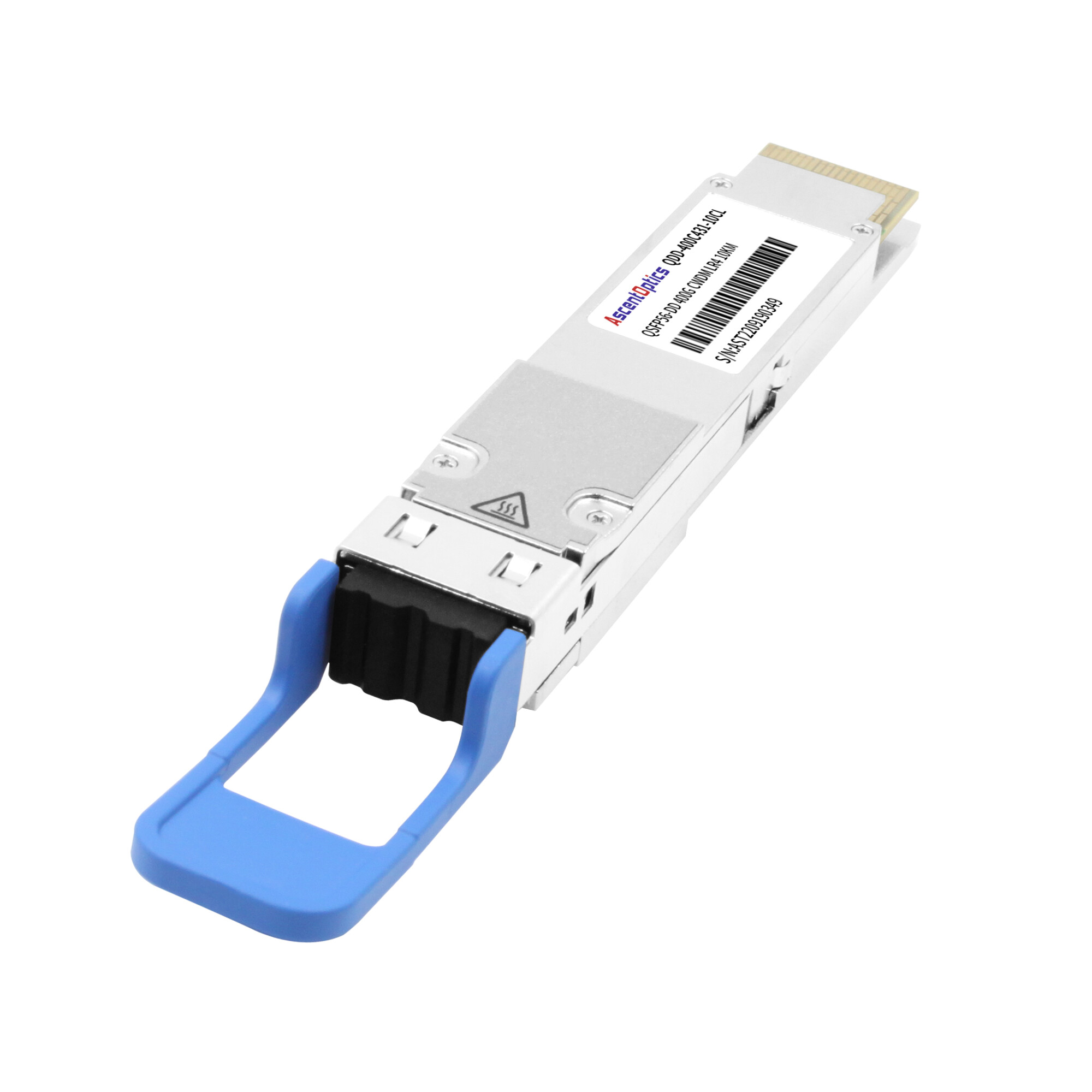
400G LR4: Long Reach
Specifications:
- •Maximum distance: 10km
- •Fiber type: Single-mode fiber (SMF)
- •Connector: Duplex LC
- •Wavelengths: 1271nm, 1291nm, 1311nm, 1331nm (CWDM4)
- •Power consumption: 12–15W
- •Standard: IEEE 802.3bs, 100G Lambda MSA
400G LR4 uses the same CWDM4 wavelength plan as FR4 but utilizes higher-power electro-absorption-modulated lasers (EML) and enhanced DSP for greater link distance. These optical elements hold up to a 10 km range and require much higher-specification lasers and tighter tolerances.
Best for:
- •Metro data center interconnect (DCI)
- •Telecom backhaul and aggregation
- •Cross-campus links exceeding 2km
- •Applications requiring guaranteed 10km reach with margin
Cost consideration:
LR4 modules typically cost 30–50% more than FR4 due to higher-specification optical components. Unless you need beyond 2km reach, FR4 offers better value.
Quick Comparison Table
| Parameter |
SR8
|
DR4 |
FR4 |
LR4
|
| Max Distance |
100m (OM4)
|
500m |
2km |
10km
|
| Fiber Type |
MMF
|
SMF |
SMF |
SMF
|
| Connector |
MPO-16
|
MPO-12 |
Duplex LC |
Duplex LC
|
| Optical Lanes |
8
|
4 |
4 (CWDM) |
4 (CWDM)
|
| Wavelength |
850nm
|
1310nm |
1271–1331nm |
1271–1331nm
|
| Power |
6–8W
|
8–10W |
8–12W |
12–15W
|
| Relative Cost |
Lowest
|
Low |
Medium |
High
|
| Breakout |
No
|
4×100G |
No |
No
|
Compare 400G FR4 and LR4 specifications in detail →
How to Choose the Right 400G QSFP-DD Transceiver Types
Selecting the optimal transceiver requires systematic evaluation of four key factors.
Step 1: Determine Transmission Distance
Start with your physical link distance, then apply these rules:
- •≤100m: SR8 (if MMF exists) or DR4 (if SMF exists)
- •100m–500m: DR4 (most cost-effective)
- •500m–2km: FR4 (optimal cost-performance)
- •2km–10km: LR4 (required for beyond 2km)
Important: Add 20% distance margin for patch cords, slack, and future rerouting. A 1.8km link should use LR4, not FR4, to ensure reliable operation.
Step 2: Evaluate Your Fiber Infrastructure
Your existing fiber plant heavily influences transceiver selection:
Multimode fiber (orange/aqua jacket):
- •SR8 is your only 400G option
- •Consider MMF replacement vs. SR8 cost trade-off
Single-mode fiber with MPO-12:
- •DR4 leverages existing infrastructure
- •Supports 4×100G breakout for migration
Single-mode fiber with LC connectors:
- •FR4 or LR4 depending on distance
- •Most flexible for future expansion
In 2024, Beijing’s administration cloud company demonstrated a remarkable increase in operating centers in Zhangjia-Kou. The more staggering beginning was the contractor laying OM4 multimode fibers. “Our preference was going to be 400G QSFP-DD modules,” mentioned NEPA Network Data Communication collar Li Wei. “However, the range of 100 meters implied by the modules provided within 400G QSFP-DD and the cones of SR8 did not help us always with any aggregation switches being brought within that range. So replacing all the fiber to support the DR4 with a single mode, it was not necessary as the extra cost for installation of additional switches for navigating the range constraints of SR8.”
Step 3: Power and Thermal Planning
400G transceivers consume significantly more power than 100G modules. A fully populated 32-port 400G switch can draw 320–480W just for optics.
Power budget guidelines:
| Configuration |
Power per Module |
Total Switch Power |
| 32× SR8 |
6–8W |
192–256W |
| 32× DR4 |
8–10W |
256–320W |
| 32× FR4 |
8–12W |
256–384W |
| 32× LR4 |
12–15W |
384–480W |
Thermal considerations:
- •Ensure 400W+ thermal headroom per switch for optics alone
- •Validate airflow direction matches transceiver heat sinks
- •Monitor DOM (Digital Optical Monitoring) temperature thresholds
- •Plan for 5–10°C temperature rise in densely packed cages
Step 4: Cost-Performance Analysis
Beyond module cost, consider total cost of ownership:
Fiber infrastructure costs:
- •MPO-16 trunks (SR8): Higher fiber count, specialized connectors
- •MPO-12 trunks (DR4): Standard parallel optics infrastructure
- •Duplex LC (FR4/LR4): Lowest fiber count, standard patch cords
Operational costs:
- •Power consumption over 5-year lifecycle
- •Cooling energy for additional heat load
- •Maintenance and replacement logistics
Migration path:
- •DR4 breakout enables 400G-to-100G interoperability
- •QSFP-DD backward compatibility protects investment
- •800G-ready platforms extend lifecycle
Selection Decision Matrix
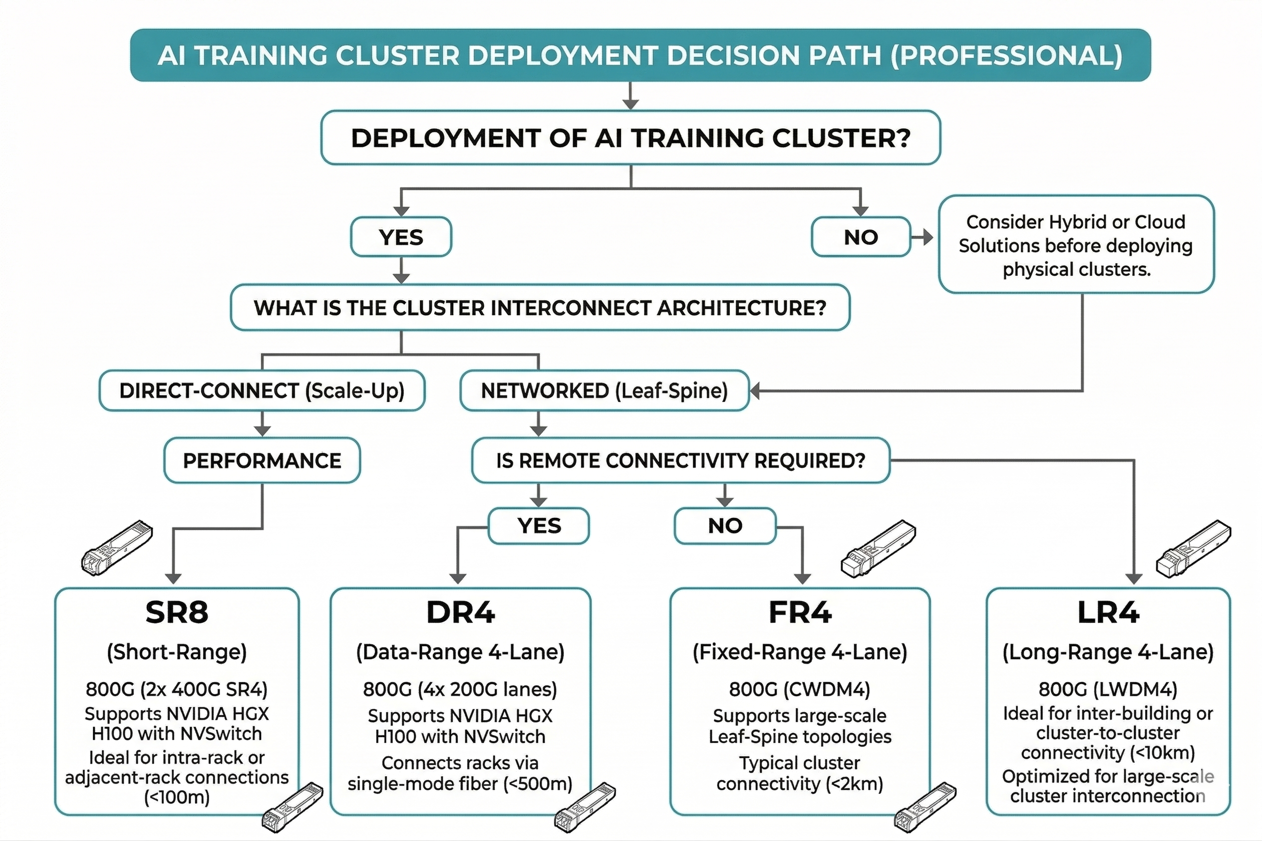
Use this decision tree for any 400G deployment:
1.Do you have multimode fiber only?
- •Yes → SR8 (under 100m) or replace fiber
- •No → Continue
2. Is distance under 500m?
- •Yes → Do you need 4×100G breakout
- Yes → DR4
- No → FR4 (if SMF with LC exists) or DR4
- •No → Continue
3. Is distance 500m–2km?
- •Yes → FR4 (optimal choice)
- •No → Continue
4. Is distance 2km–10km?
- •Yes → LR4
- •No → Consider coherent optics (400G ZR)
Request a quote for your 400G deployment →
400G Deployment Patterns and Use Cases
AI/ML Training Clusters
Modern AI training infrastructure represents the fastest-growing 400G deployment segment. Large language model training requires connecting hundreds or thousands of GPUs with high-bandwidth, low-latency interconnects.
Why FR4 dominates AI fabrics:
- •2km reach covers most cluster sizes without repeaters
- •Duplex LC simplifies cable management vs. MPO
- •Lower power consumption critical in dense GPU racks
- •Cost-effective at the massive scale AI requires
Deployment example:
A typical 1,024-GPU training cluster using NVIDIA DGX H100 systems requires approximately 512 400G links for the fabric. At this scale, choosing FR4 over LR4 saves $200,000+ in module costs alone.
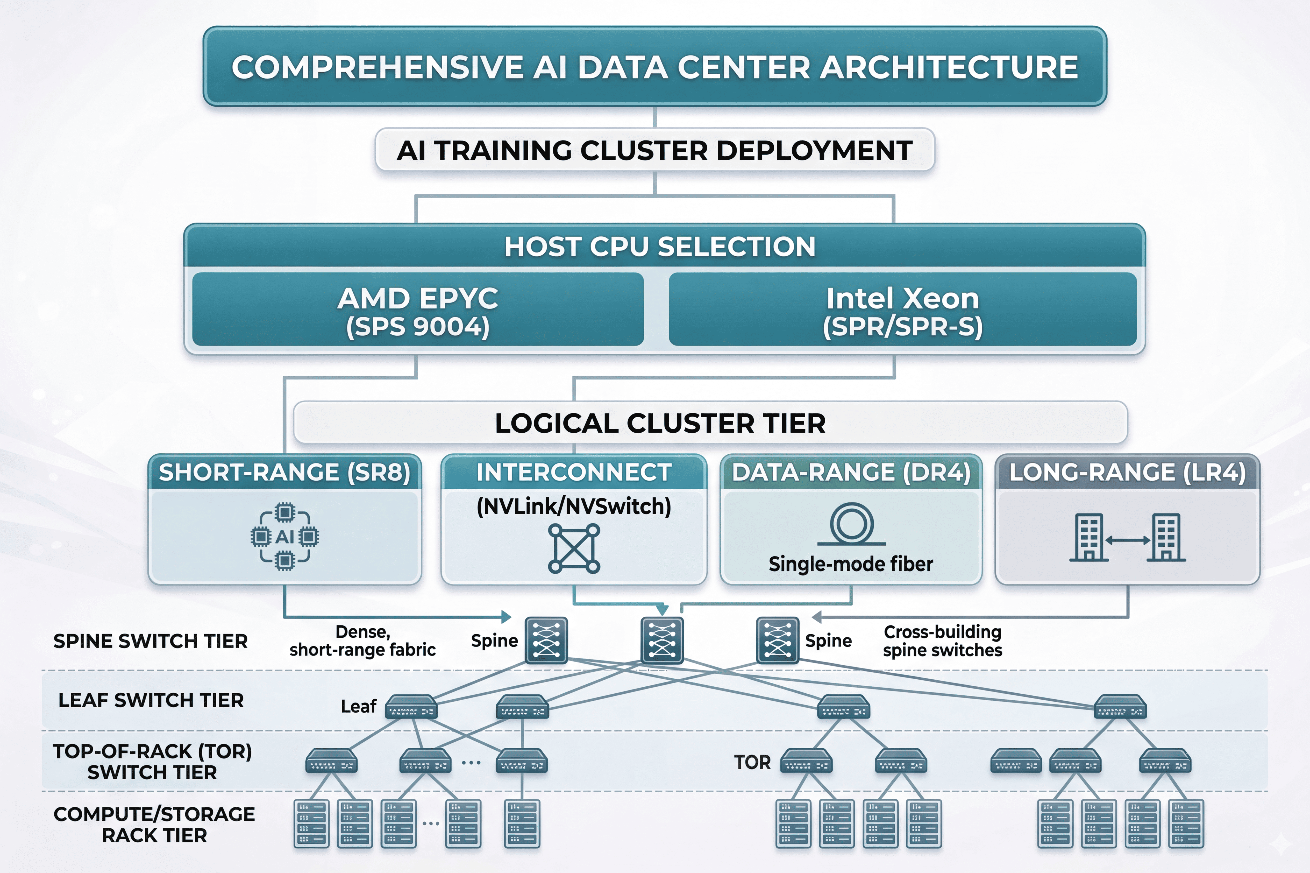
Hyperscale Data Center Spine-Leaf
Spine-leaf architectures in cloud data centers use 400G for both leaf-to-spine and spine-to-core connectivity.
Typical configuration:
- •ToR to Leaf: 100G (or 400G with breakout)
- •Leaf to Spine: 400G FR4 or DR4
- •Spine to Core: 400G FR4 or LR4 depending on distance
The DR4’s breakout capability enables gradual migration. A leaf switch with 400G uplinks can connect to 100G spine infrastructure during the transition period, protecting existing investments while enabling future 400G spine upgrades.
Data Center Interconnect (DCI)
Campus DCI links connecting multiple facilities require careful distance assessment:
- •Same campus (<2km): FR4 dominates due to cost advantage
- •Metro area (2–10km): LR4 required for reach
- •Long-haul (>10km): 400G ZR coherent optics replace direct detect modules
Migration from 100G to 400G
Most organizations will transition gradually rather than forklift-upgrade entire networks.
Phased migration strategies:
1.Core-first: Upgrade spine/core switches to 400G, maintain 100G at edge
- •Use DR4 breakout to connect 400G spine to 100G leaf switches
2. New build: Deploy 400G in new facilities, maintain 100G in existing
- •FR4 for cross-facility links as needed
3. Capacity-triggered: Upgrade specific links when 100G saturation occurs
- •Monitor port utilization and plan upgrades proactively
As ShopDirect, an e-commerce powerhouse in Europe, planned to redesign their network architecture for 2024, they faced one more common challenge in the history of migration: Their traffic was being transferred through 100G+ lines that accounted for merely 85% of the traffic during peak seasons, making it difficult to load and not enough money to operate at complete capacity.
“It kind of feels very surgical,” remarked Klaus Mueller, network architect for ShopDirect. “Spine switches were upgraded to 400G, and then utilizing DR4, Leaf switches were divided into all of the 100G sockets opened by them. Further down the road, the breakout ports will be decommissioned using any leaf switch that natively supports 400G access of the user. This is costly and time-consuming, but deals that the finance guys just love.”
Power Consumption and Thermal Considerations
Understanding 400G Power Profiles
The shift to PAM4 modulation significantly impacts power consumption. While 100G QSFP28 modules typically consume 3.5–4.5W, 400G QSFP-DD modules require 2–3× more power.
Power breakdown by component:
- •Laser diodes: 20–30% of total power
- •DSP/gearbox: 30–40% of total power
- •TIA/driver electronics: 15–25% of total power
- •Control/monitoring: 5–10% of total power
Form factor efficiency improvements:
- •Early QSFP-DD FR4: 12W typical
- •Modern QSFP-DD FR4: 8–10W
- •QSFP112 FR4: ≤9W (smaller form factor, improved thermal design)
Thermal Management Best Practices
High-density 400G switches require careful thermal planning:
Airflow considerations:
- •Use switches with front-to-back or back-to-front consistent airflow
- •Avoid mixing airflow directions in the same rack
- •Ensure 400G transceiver heat sinks align with airflow path
Temperature monitoring:
- •Monitor DOM temperature readings proactively
- •Set alerts at 70°C (typical max is 85°C)
- •Plan thermal shutdown procedures for overheating conditions
Rack layout:
- •Distribute high-power modules across the switch rather than clustering
- •Consider external fan trays for especially dense deployments
- •Leave 1U empty above/below high-density 400G switches when possible
Future-Proofing: QSFP-DD and Beyond
800G Migration Path
QSFP-DD was designed with 800G in mind. QSFP-DD800 uses the same mechanical form factor but increases per-lane speed to 100 Gbps PAM4 (8 × 100G = 800G).
Key considerations:
- •QSFP-DD800 modules require QSFP-DD800-capable switches
- •Power consumption increases to 15–20W per module
- •Thermal design becomes even more critical
- •Backward compatibility maintained for investment protection
Emerging Standards
Linear Drive Pluggable (LPO):
LPO modules eliminate the DSP to reduce power consumption and latency. By moving signal processing to the switch ASIC, LPO modules can achieve 30–40% lower power than standard DSP-based modules.
Trade-offs:
- •Reduced reach (typically 2km max)
- •Requires compatible switch ASICs
- •Limited vendor interoperability
- •Best for controlled environments (hyperscale data centers)
Coherent Optics Integration:
400G ZR and ZR+ standards bring coherent detection to pluggable modules, enabling 80km+ reach without external transponders. These modules use more sophisticated modulation (16-QAM) and DSP but extend 400G to metro and regional networks.
Conclusion
Selecting your 400G QSFP-DD means taking into account four key parameters: operation mode, connectors, power, and cost. Very limited applications for multimode SR8 short-reach scenarios would trigger few data centers to choose DR4 (useful where MPO infrastructure and breakout are necessary), FR4 (optimal cost-performance for 1-2km), or LR4 (for >2km city-to-city links) under the right acceptance or conditions.
Key takeaways:
- •Match distance to specification: SR8 (100m), DR4 (500m), FR4 (2km), LR4 (10km)
- •Consider fiber infrastructure: MPO-12 for DR4, duplex LC for FR4/LR4, MMF for SR8
- •Plan for power: 400G modules consume 2–3× more power than 100G—validate thermal design
- •Optimize for TCO: FR4 offers the best value for 1–2km links; LR4 only when necessary
- •Enable migration: DR4 breakout supports phased 100G-to-400G transitions
It is imperative to recognize the battle of interests due to the enormous investments in AI training clusters and hyperscale data centers, which have driven the 400G connectivity demand uphill. There is an irresistible pointer that, according to an analysis from the public marketplace, a trillion dollars of the former stove would thus have gone to advances in 2025. Whether or not there are instances of 800G in the on-ramp, 400G will have to be maintained on a virtual fast ladder.
Are you considering rolling out the 400G network? Check out the Optics engineering services’ staff with respect to distance supplied, fiber connector, and Ascent Optics but offer better advice to utilize the optimum solution on the QSFP-DD based transceiver. For only the price regarding the article is significant for consideration, 400G QSFP-DD SR8, DR4, FR4, and LR4 should be on your radar.
Contact Our 400G Optical Networking Experts →
Frequently Asked Questions (FAQs)
1. What exactly is a 400G QSFP-DD optical module?
A 400G QSFP-DD optical module is designed to setup high-density transceiver modules on 400-gigabit Ethernet Links. It utilizes the QSFP-DD form factor, providing 400g ports for data center and compute interconnects through various links such as multi-mode fiber (MMF/OM3/OM4) and single-mode fiber (SMF) to suit longer lengths. The varieties include SR8, DR4, LR4, LR8, XDR4, and ER8 modes that are IEEE-standard-yet-ieee 802.3bs-compliant and implied for 400G networks or deployment of 400-gigabit Ethernet.
2. How do 400G QSFP-DD transceivers differ (SR8, DR4, FR4)?
The exceptional technicalities of 400g QSFP-DD optical transceivers are wavelengths, traffic pattern groups, and reach. SR8 modules (400gbase-sr8 qsfp-dd pam4) opt for 8 x 50G on MMF (850nm 100m on OM4/OM3) with MPO-12 connectors for up to 100m; DR4 and FR4 single-mode-based modules give both the ability to provide 500m to several kilometers of reach, depending on the version. DR4 uses typically 4 lanes per direction (4 x 100G), and the others, like FR4 and LR4, are aided by WDM technologies for very long reaches (the latter capable of length of 10km for LR4 into SMF).
3. Can 400G QSFP-DD SR8 modules reach 100m over OM4 or OM3?
Yes, 400G QSFP-DD SR8 optics with pam4 850nm 100m specifications can cover 100m over OM4 (usually OM3 because of host-margin power). The sr8 transceivers run 8 x 50g lanes on MPO-12 and are commonly designated as 850nm 100m on multi-mode fiber, therefore designed for blessings to scale up along the data-center topologies in the switch architecture.
- IEEE 802.3bs standard
- QSFP-DD MSA
Post Views: 11