Voltage variable attenuators (VVAs) are essential in engineering radio frequency (RF) and signal transmission control. Such devices control the level of RF signal amplitude with minimum distortion and loss of signal. The working of voltage variable attenuators includes the combination of different electronic principles, such as variable resistive networks or active circuitry, which allows the engineers to adjust the amplitude level from a great variety of devices, from telephones to radio stations. This article aims to offer a detailed understanding of RF and voltage variable attenuators, including their working principles, areas of use, and design specifics relevant to current RF applications regardless of the level of scope of the engineer in this field, whether a novice or an experienced engineer, knowledge about these devices is unsuitable for power management and improvement of communication systems in demand.
What is a Variable Attenuator?
Understanding Variable Attenuators
A variable attenuator is a device that helps to reduce the strength of a signal systematically. Unlike fixed attenuators, which yield a specific attenuation level irrespective of time, variable attenuators give a user the option of selecting the extent of attenuation debts and, hence, are more flexible in dealing with signals. These elements can be made with resistive, capacitive, or inductive elements and are primarily found in RF systems to adjust the signal strength levels to meet a particular need and avoid interference. However, one must know how to determine the effectiveness of variable attenuators for any specific application installed by looking at the frequency range, its insertion loss, and, most importantly, the range of attenuation levels that can be achieved.
Common Applications of Variable Attenuators
Variable attenuators find multiple applications in both commercial and industrial uses. In particular, telecommunication systems adjust signal levels in transmitting lines to deliver adequate power without overloading the system and causing distortion or interference. In broadcast engineering, such devices are widely and often used to keep the level of audio and video perpetual at the receiving end by varying the strength of the signals transmitted through the RF paths. They are, therefore, also used in laboratories for the measurement and calibration of some equipment whereby the technicians can create different signal conditions. There are also other uses, such as within an electronic warfare system where additional signal control is necessary for radars and communication systems and wireless networking where the quality of service is guaranteed by reduced signal deterioration.
How Variable Attenuation Works
Variable attenuation, as the term implies, also controls the amplitude level of a radio frequency signal but with little or no regard to the geometry of the signal. This can be accomplished using regular or active resistors that change the resistance level automatically. An attenuator reduces the output value of a signal because its construction involves several heat-producing elements. The amount of attenuation is changeable so that the user’s needs are satisfied, such as avoiding overdrive in receptors or balancing the signals coming to different devices. Such capabilities are needed in numerous situations so that the quality of the transmitted signal is as high as possible and all types of distortions are minimized.
Different Types of Variable Attenuators
RF Variable Attenuators
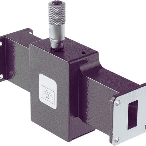
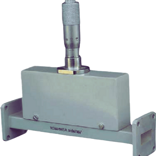
RF variable attenuators are often present in any RF setup to provide maximum or minimum power imposed on the radio frequency signals in different systems. Such devices help in adjusting the power of a transmission, which is of interest in cellular, satellite, or broadcasting networks. Manually operated and automated, the RF variable attenuators can be classified as the primary varieties based on the operational modes displays and electronic variable RF attenuators, with the latter sometimes having auto-adjust servo mechanisms.
Present-day manually operated RF variable attenuators usually consist of several dial-controlled potentiometers, which allow users to choose a given attenuation level as per their choice. As opposed to physical potentiometers, most electronic RF variable attenuators use friendly microprocessor controls, which can adjust the RF signal more efficiently using the feedback of respective measurement systems. Both are available for application over a wide frequency and power range parameters, providing efficient signal management while minimizing distortion. Such versatility justifies using RF variable attenuators where RF communications are in dire need of continuity in several adverse conditions.
Voltage Variable Attenuators
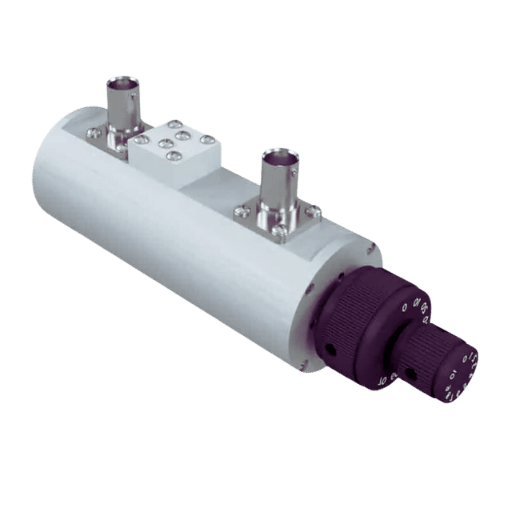
Voltage variable attenuators (VVAs) are devices in analog and digital signal processing circuits that reduce the signal’s power by an input control voltage. Fixed attenuators, which apply the same amount of attenuation at all times, are rigid and cannot be changed. These devices are known as voltage variable attenuators since they allow all adjustment requirements.
Most features come as either resistive voltage variable attenuators or capacitive voltage variable attenuators, where each solution has a unique frequency range operation, even where a narrow band is necessary. A basis of resistive VVAs is to change the input resistance according to the bias to attenuate the output signal. Capacitive VVAS, in the same manner, integrates capacitors for minor attenuation, which is highly applicable in applications that require high speeds and efficiency in performance.
The factors that influence the design and selection of voltage variable attenuators include the ill factors, which are always necessary in engineering, the need to control the signal amplitude, and the risk of introducing undesirable noise or distortion. VVAs have proved to be versatile, so designers can design them based on the application they are needed for, extending from the use in Obado electronics to high-end communication, making them relevant in modern electronics design practice.
Optical Attenuators
Active optical attenuation devices are components of an optical communication system that reduce the optical power without having to turn off the system. In the systems, reducing brightness helps prevent optical detectors from becoming saturated and maintain acceptable signal levels. Generally, there are three types of optical attenuators: fixed, variable, and programmable. Fixed optical attenuators provide a constant amount of attenuation, making them ideal for most applications requiring constant performance. Attenuation using variable optical attenuators (VOAs) can be performed almost continuously to respond to signal changes. There are reprogrammable optical attenuators, which are more sophisticated as they allow the customer to select the attenuation function within the system through a program.
The selection of an optical attenuator depends on several parameters, such as the light wavelength, possible respect for the minimum reach of the signal, and actual use in telecom, fiber optic networks, or equipment under test. Apart from satisfying the required signal levels, these devices also help reduce the amount of reflection that occurs, thereby contributing to the system’s robustness.
How to Choose a Variable Attenuator
Key Design Considerations
While picking a variable optical attenuator (VOA), some critical design aspects must be addressed so that the desired performance is achieved in a given application.
- Attenuation Range: The range of attenuation that the device is capable of working at is of paramount importance. One needs to ascertain that the specific device under this application can provide the requisite attenuation so that the system’s level of performance is preserved.
- Wavelength Compatibility: Various systems of optical communication employ different wavelengths. The wavelengths handled by the varying optical attenuator must conform to the design so as not to blind the quality of the signals.
- Response Time: The response time of the VOAs becomes important when the signals’ states need to be constantly changed. Signal management becomes smarter with short response times because light input change within a given time frame compensates.
- Insertion Loss: This is defined as a shift in performance when the attenuator is used in the system. It is also applicable when VOAs are utilized and should, therefore, be improved in every way possible to preserve the transmission system’s overall performance.
- Mechanical and Thermal Stability: VOAs should be built to endure the mechanical stresses encountered during field operation, with the expectation that performance uniformity will be experienced over a temperature range.
- Control Interfaces: The type of control—manual, electronic, or software—will determine its accuracy and how well it will be integrated into the existing architecture.
- Machines and Controls: The physical size and shape of the apparatus have some bearing on how and to what extent the attenuator can be used in a particular system, especially for space-limited applications.
These considerations allow engineers to thoroughly justify their choice of the optical variable attenuator and its applications elsewhere, increasing the efficiency and effectiveness of the systems designed.
Understanding Attenuation Range
The range of attenuation of a Variable Optical Attenuator (VOA) signifies the range in which the component effectively reduces optical signal outpower without introducing distortion errors. The measurement of the attenuation range is usually in dBs and is among the significant parameters that now control the efficacy of the VOAs in any given optical network. Most quality VOAs can give degradation ranges from as small as 0.1 dB to values exceeding thirty dB, but this will depend on the design and application of the attenuators.
In practice, a more extensive attenuation range achieves more salability to control the signal level in different conditions of the network, and this is more useful in variable scenarios where the conditions of the network and or weather are liable to change. Acquisition of any suitable VOA entails determining how much attenuation range is acceptable for the application to ensure that signal quality and effectiveness are not compromised in the communication system, particularly within microwave and millimeter wave systems. Thus, it becomes essential to accommodate the attenuation capacity of the VOA to the technical requirements of the network topology to be implemented.
Connector Types and Compatibility
It is essential to remember the connector types and their compatibility when choosing a V O A since they affect the existing optical systems’ composition. SC, LC, ST, and MTP/MPO are some of the standard connectors found in optical networks, and there must be no signal loss due to incompatibility with these connectors. Not all the connectors for the V O A should be fitted on the V O A unit in use as connectors that do not have a corresponding connector on the connecting fibers, which increases the loss of the entire system as well as its performance.
Also, due to its usage, a VOA may come with either non-removable or removable connectors that may ease the deployment of the devices. Moreover, connector misalignment, insertion loss, and return loss are other parameters that need to be taken into consideration as they affect the overall signal management effectiveness in the optical network. Even more, since the installation of the preferred VOA is made easier by having suitable connectors, the performance of the optical communication system is bound to improve.
Installation and Setup
How to Properly Mount Variable Attenuators
Attention to the mechanically robust and well-placed Variable Optical Attenuator (VOA) is essential for effectively functioning the components in an optical communication system. First, one must decide on a location that will cause the most minor interference on the already established optical paths and yet afford reasonable access for movement.
- Prepare the Site: Make certain that the location where the device will be installed is free of dust or dirt, as this can adversely affect the attenuator’s functioning and lifespan. Gather all the tools and equipment needed for the installation to avoid interruptions during the mounting activity.
- Align the Optical Path: Fix the optical fibers inside the system at the vox in the same direction as the lightning volt amplifier. This will help avoid any possible loss. When tuning equipment is used, such alignment is made possible.
- Connect the Fiber Cables: Input or output fiber optic cables should be plugged into the VOA with the applicators’ attention to ensure which connector goes to which port and if all plugs are tight. Do not twist too much so that the fiber connectors and the fiber are not damaged.
- Test the Installation: As soon as the device is mounted, a test must be conducted to check if the Variable Optical Attenuator performs its intended function. For this test, signal attenuation meters are recommended for accurate readings.
- Last Modifications: In case of any initial test results, consider making changes, if any, to the attenuation settings to get maximum performance results. Update the configuration to the log for additional reference or troubleshooting later on.
If you follow these steps, it will be guaranteed that the Variable Optical Attenuator is also fitted correctly, enhancing the efficiency and reliability of the optical communication systems.
Manual and Automatic Control Options
When considering control options for Variable Optical Attenuators (VOAs), both manual and automatic control have respective benefits.
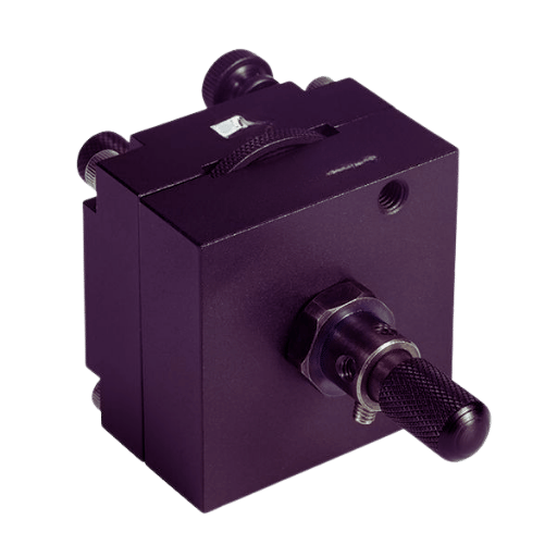
- Manual Control Options: These systems allow for direct human interaction with the attenuation settings through cognitive processing methods such as rotating knobs and moving sliders. Operators have been known to set various levels of attenuation by simply manipulating the knobs or sliders provided in the devices. This way of working offers the user quick feedback and the ability to work more flexibly, thus being a good fit in cases where accuracy and time constraints are also at play. However, the manual control alternative is also labor intensive and time-consuming, so an operator must always pay attention to it.
- Automatic Control Options: When it comes to automatic VOAs, however, electronic circuitry and software algorithms can be incorporated to control the attenuation depending on the feedback from the optical system. Connecting to network management protocols and integrating ATTC with VOAs makes the adjustment possible without manual help, increasing performance uniformity. On the contrary, AVV systems can react more quickly to such varying signal conditions in telecommunication systems and maintain the signal integrity for much longer. This is important in applications where the demand is high.
Given that optical networks have manual and automatic control options, the specific operational requirements for rendering the service, such as precision and responsiveness, and the figure increments of optical integration in the network determine the choice made.
Testing and Calibration Tips
There are many methods and procedures to test or calibrate the Variable Optical Attenuators (VOAs), and all of these procedures aim to enhance the use of VOAs in an optical communication network. However, some few pointers gathered from the best articles in this field are as follows:
- Baseline Measurements: Measure the attenuation at various positions using a calibrated optical power meter to create a baseline level of attenuation to be used as a reference for comparing the results obtained at various other assessments in the future.
- Regular Calibration: Conduct VOA away from the factors that contribute to the wear and tear of the optical simulator to get consistent attenuation values. Standards controllable to/governed by the national measurement system should be employed as this improves the accuracy and reliability of the calibration.
- Environmental Considerations: The test must be done under competent environmental conditions, such as temperature and humidity, that affect the optical characteristics of the passive devices being tested. Make Log Book Entries to account for the effects of attenuation soldering conditions.
- End-to-end Testing: Perform complete end-to-end testing of the optical communication system, considering all peripheral devices work. This will assist in marking areas where the attenuation performance may not meet the expected performance, thereby requiring corrective measures or other changes.
- Documentation: All actions concerning the testing or calibration should be documented neatly and in order, including target test results, results obtained, settings, etc., and any changes made, if any. This documentation is crucial for reference in future repairs and maintenance while observing the course set by the industry.
If operators follow these testing and calibration guidelines, they can greatly improve the dependability and efficiency of VOAs within their optical networks.
Troubleshooting Common Issues
Identifying Insertion Loss Problems
Insertion loss is the loss of signal power normalized, usually in dB, through a device on a transmission line. In optical communication systems, there is a need to locate insertion loss since it causes several problems, and for this purpose, a stepwise approach must be adopted:
- Make a General Inspection: With respect to all connections, fibers, and components, look for signs of damage, dirt, or any other distortion that might be evident. In many cases, such basic components as deficiencies in the cleaning or alignment of connectors can address the problem, even before further tests.
- Apply an Optical Power Meter: The input and output optical powers of that device are being measured to determine how much of the power was “lost” to ensure the insertion loss was accurately set. It is necessary to compare the aforementioned thresholds with the device’s insertion loss to determine Scott components participating in the loss.
- Consideration of Reflection Losses: Insertion loss, which is the main aspect, should also be supported by ensuring that reflection due to poor connections or disorders, such as mismatches of components, is well taken care of. It is useful to use OTDR (optical time domain reflectometry) to detect reflecting points along the length of a light guide.
- Review Underlying Fiber Bends and Splice: Inter-fiber angle excess stressing or a suboptimal splice procedure could also be a factor in extra cuts. Here, an assessment of the fiber path will be performed to identify curvature complying with the manufacturer’s cut-off and ensuring a suitable condition of splicing.
- Document Findings: Keep records of measurements, conditions, and any observations taken during the tests. This documentation is useful in determining patterns or reoccurring problems that will improve the defects rectification process in the future, especially with regard to benchtop setups.
These recommendations are intended to enable the operators to quickly locate and correct the causes of insertion loss problems, thus increasing the efficiency of the optical system in general.
Resolving Connector Compatibility Issues
Problems related to connector compatibility are some of the significant factors that help preserve the reliability of optical fiber systems. To overcome these issues, follow these guidelines.
- Identify Connector Types: Start with connector diseases such as LM-Lite, LC-types, SC, and ST and contribute MRT/MPT-oriented toward cooperative behavior. Each has certain designs and connections to be made, which may change routing connections if used.
- Use Auxiliary Plates: Where connectors mismatch, use adapter plates or hybrid connectors to bring about interconnections that would have otherwise been impossible without loss of signal. Use adapters that conform to the industry’s specific requirements, if any.
- Study the Remote Ends of Connectors: Use a microscope to examine the cleanliness and state of the remote ends of connectors. Moisture contamination of connectors leads to additive reflection losses even after the rotation of rotational contacts. Regular clean-up of the connectors using the approved methods and end-face prevention are necessary for performance.
- Check for Manufacturer’s Recommendations: Plug your product into the manufacturer’s recommendation and fragmentation information, such as the levels of insertion loss and return loss, in their characteristics for use. This helps ensure that the selected implants are in line with the socket available in the electrical circuit’s designed architecture.
- Testing Procedure: After installing new connectors or adapters, test them with an Optical Power Meter to ensure that the connection quantitatively meets the acceptable loss criterion. This provides the proper functioning of the system and helps anticipate failures.
These practices will assist technicians in addressing connector compatibility issues, thus preventing the degradation of optical network performance and reliability.
Tips for Maintaining Desired Attenuation
- Proper Installation Techniques: Proper installation techniques are required to ensure that the connectors and cables do not become physically stressed or grounded, which increases attenuation. Additionally, adhere to the management of the installation processes in terms of cabling configurations and the recommendations for the different connector types.
- Regular Inspection and Testing: Ensure that this includes checking for any holes that could be present in the made-up optical fibers that could impact the signal quality. The optical cables and connectors should be routinely inspected and tested for aging, extreme power levels, and physical damage. Instruments like the Optical Time Domain Reflectometer (OTDR) should be applied to evaluate factors that look for darkness and to evaluate degradation all over the fiber.
- Environmental Considerations: Fiber optic installations should not be exposed to extreme temperature and moisture conditions that will cause them to lose their utility over time. Ensure all cables are completely covered with a conduit or a heat-resistant and moisture sheath to protect them from water, high temperatures, and physical trauma.
Through these methods, the attenuation level can be commendable; therefore, maintenance of the dependability and durability of the performance of the optical communication systems will be enhanced.
Reference Sources
Decibel
Attenuator (electronics)
Attenuation
Frequently Asked Questions (FAQs)
Q: What is a Voltage Variable Attenuator?
A: A Voltage Variable Attenuator (VVA) is a type of device that enables the control of signal power reduction in a microwave or RF signal path by varying a Direct Current (DC) voltage. One important use is in instances where the signal level needs to be varied over time.
Q: What is the effect of 50 ohm impedance on RF attenuators?
A: 50 ohm impedance is the most used impedance, especially for RF purposes, as it is required for maximum power dispatch and power dispersion. This impediment is very important in protecting signal quality, hence enhancing performance in the RF attune.
Q: Can it manually set the attenuation level provided by rotary attenuators?
A: Yes, functional, also known as manually adjustable rotary attenuators, have an additional knob or dial for adjusting only the level of attenuation. This helps in controlling the desired level of output signal.
Q: What is the operating frequency range for RF attenuators?
A: Ordinary RF attenuators can function within a wide bandwidth, from the baseband up to 18 GHz or more. Hence, they are not restricted to microwave and millimeter wave technology applications only. The specific frequency range depends on the attenuator’s model and design.
Q: In more straightforward English, what does a dual-mode RF attenuator do?
A: A dual-mode RF attenuator means there are two different modes of attenuation—two alternative methods of controlling the signal attenuation. This allows the user of the device a little flexibility for switching purposes as per their requirements.
Q: What is the typical dynamic range of a continuously variable attenuator?
A: It is possible to have a wide dynamic range that is continuously variable up to 30 dB or even more. This extends the range of tuned fine signals to meet the output level wanted.
Q: Is it possible to get customized RF attenuators?
A: Yes, various RF attenuators can be custom-manufactured for particular needs, such as non-standard impedance values, certain frequency bands, or specific connectors. You are encouraged to talk to the manufacturer, specify your needs, and ask for a quote.
Q: What are the most common types of connectors used for RF antennas?
A: Common connectors used in RF Splitters include SMP, N connectors, and BNC, among others. These connectors are most commonly used due to their smaller size and good performance at high frequencies.
Q: What is return loss regarding RF attenuators?
A: Return loss quantifies how much of the feedback signal is actually received at the unit’s input. A high return loss means decreased return of the signal at the source, which signifies better performance in which no reflection of the signal takes place.
Q: When will the estimated delivery date for the RF Attenuators that will be ordered later be?
A: When an order with required RF attenuators in stock is usually made, it gets dispatched in two to three working days. However, in some cases, lead times may differ, depending upon the order undertaken and the configuration of the model as well. To obtain more details, don’t hesitate to get in touch with the supplier directly.
Post Views: 4,798


