The purchase order had already been signed. The eight hundred forty-seven QSFP modules sat in their boxes awaiting deployment in the 12 racks in the new data center. That was when Sarah, the lead network architect at a fast-growing cloud provider, uncovered the critical difference between QSFP-DD and QSFP112. The switches that they had selected supported QSFP112, yet their procurement crew had gone ahead and ordered QSFP-DD modules based on an incomplete cross-vendor compatibility matrix. Although appearing nearly identical and fitting into the same cages, these two form factors differ electrically. The error ended up costing them three weeks of delay and a restocking fee of $47,000.
When designing a 400G infrastructure, network engineers typically choose between QSFP-DD and QSFP112. The difference goes far beyond physical appearance — it affects electrical signaling, power consumption, thermal performance, and long-term upgrade paths. Both deliver 400 Gigabit Ethernet, but their architectures are not equal. A wrong choice can disrupt deployment and increase total cost of ownership.
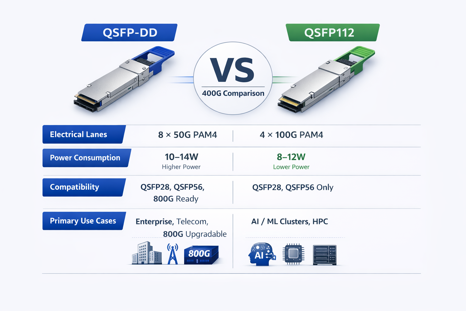
Here is a complete QSFP-DD vs QSFP112 comparison: 8-lane vs 4-lane electrical designs, backward/forward compatibility, energy efficiency, thermal characteristics, and vendor ecosystem support.
At a Glance: QSFP-DD vs QSFP112 Key Differences
Before diving into the QSFP-DD vs QSFP112 technical details, this comparison table summarizes the essential differences between these 400G form factors.
| Specification |
QSFP-DD |
QSFP112 |
| Electrical Interface |
8 × 50G PAM4 |
4 × 100G PAM4 (112G capable) |
| Aggregate Bandwidth |
400 Gbps / 800 Gbps |
400 Gbps |
| Typical Power Consumption |
10–14W |
8–12W(typically 2–4W lower) |
| Dimensions |
18.35 × 89.4 × 8.5 mm |
18.4 × 89.4 × 8.5 mm |
| Backward Compatibility |
QSFP28, QSFP56, QSFP112* |
QSFP28, QSFP56* |
| 800G Support |
Yes (QSFP-DD800) |
No |
| Primary Applications |
Enterprise DC, telecom, mixed environments |
AI/ML clusters, HPC, greenfield 400G |
| Leading Vendors |
Cisco, Juniper, Arista (enterprise) |
NVIDIA/Mellanox, Arista 7500R3 |
*Backward compatibility requires switch-side support for the respective signaling rates.
Critical Compatibility Warning
QSFP-DD and QSFP112 modules are not electrically interchangeable, even though they share near-identical physical dimensions and fit into the same QSFP cages. QSFP112 modules can physically occupy a QSFP-DD cage, but they will only function if the switch ASIC supports 4×100G (112G-capable) electrical lanes. Conversely, QSFP-DD modules require 8-lane support. Always verify electrical interface support in the switch datasheet — never assume compatibility based on physical fit alone.
QSFP-DD vs QSFP112: Electrical Architecture Deep Dive
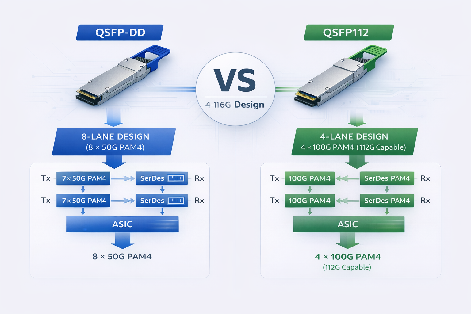
The core difference lies in electrical lane configuration, which impacts signal integrity, power, routing complexity, and upgrade paths.
QSFP-DD: 8-Lane Design (8 × 50G PAM4)
QSFP-DD (Quad Small Form-factor Pluggable Double Density) uses eight electrical lanes at 50 Gbps each (PAM4), delivering 400 Gbps total.
Technical Implementation:
- •Lane Configuration: 8 transmit + 8 receive lanes
- •Signaling Rate: 50 Gbps per lane using PAM4 (Pulse Amplitude Modulation 4-level)
- •Total Bandwidth: 400 Gbps (8 × 50G)
- •Connector: Additional row of contacts in the electrical interface for doubled lane count
The 8-lane approach has several architectural advantages. First, it provides backward compatibility with existing QSFP28 (4 × 25G) and QSFP56 (4 × 50G) modules. With the 8 lanes, the switch ASIC can negotiate down to 4 lanes for legacy modules. Second, because the doubling data lane implies that the upgrade path to 800G is simple via QSFP-DD800, which uses the same 8-lane architecture on which the per lane increases to 100G PAM4.
However, the 8-lane approach carries the disadvantage that it brings complexity. Eight data lanes will make signaling routing more challenging, require more power to drive the added number of serializer/deserializer (SerDes) circuits, or increase the thermal complexity. CMIS interface must similarly be able to manage and report on the status of twice as many electrical channels.
QSFP112: 4-Lane Design (4 × 100G PAM4, 112G capable)
QSFP112 maintains the traditional four-lane interface but increases per-lane speed to 100G PAM4 (with 112G electrical capability).
Technical Implementation:
- •Lane Configuration: 4 transmit + 4 receive lanes
- •Signaling Rate: 100 Gbps per lane (PAM4, 112G capable)
- •Total Bandwidth: 400 Gbps (4 × 112G)
- •Connector: Standard QSFP electrical interface (same as QSFP28/56)
Architecturally, a four-lane design is kept simple so that the module can cope with lane alignments with simpler signal routing and less complex operational loads connected with power modules. Essentially, power-consumer-grade QSFP112 modules largely use power 2–4 W lower than an equivalent QSFP-DD module.
Despite this, the higher per-lane speed of 112G speed presents signal integrity challenges. For the switch ASIC to support 112G SerDes, platform next-gen connection may be too restrictive. Abbasjeans states that QSFP112 support will be reliant only on newer generations of switches, which are designed along the 112G electrical signaling lines.
Signal Integrity and SerDes Considerations
The choice between 8 × 50G and 4 × 112G electrical interfaces has implications for signal integrity and switch ASIC design.
QSFP-DD Signal Characteristics:
- •Lower per-lane speed (50G) is easier to drive over PCB traces
- •More lanes spread heat generation across the module
- •Established 50G SerDes technology widely available in switch ASICs
- •Requires careful lane-to-lane skew management
QSFP112 Signal Characteristics:
- •Higher per-lane speed (112G) requires premium PCB materials and design
- •Fewer lanes reduce overall trace complexity
- •112G SerDes requires advanced process nodes (7nm/5nm) and consumes significant power
- •Shorter reach on host board traces before signal degradation
For network architects, this means QSFP-DD generally offers broader switch compatibility, while QSFP112 requires newer switch platforms but delivers power efficiency benefits.
QSFP-DD vs QSFP112: Backward Compatibility Analysis
System integration manager usually decides between QSFP-DD vs QSFP112 by considering compatibility with existing infrastructure. To lay out a preliminary plan for migration, it is essential to understand the backward and forward compatibility profiles of QSFP-DD and QSFP112.
QSFP-DD Compatibility Profile
QSFP-DD excels in backward compatibility, making it the preferred choice for brownfield deployments upgrading from 100G or 200G infrastructure.
Backward Compatibility:
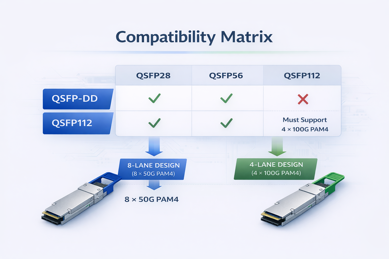
- •QSFP28 (100G): Fully compatible. QSFP-DD ports accept 100G modules and negotiate 4 × 25G NRZ signaling.
- •QSFP56 (200G): Fully compatible. Ports accept 200G modules using 4 × 50G PAM4 signaling.
- •QSFP112 (400G): Conditionally compatible. QSFP-DD ports can accept QSFP112 modules if the switch ASIC supports 112G electrical signaling.
This backward compatibility allows gradual infrastructure upgrades. Organizations can deploy QSFP-DD-capable switches now and migrate optical modules from 100G to 200G to 400G as bandwidth requirements grow, all within the same physical infrastructure.
Forward Compatibility (800G Path):
The QSFP-DD is capable of 800G is the only logical way to achieve it without the necessity of swapping out switch hardware over a period of time. That said, modularity in design between qsfp-dd800 and qsfp112 is an important concern when planning upgradation of infrastructure into the future. The QSFP-DD800 modules implement the same 8-lane architecture but see speeds decided by a 100Gs per lane in a PAM4, adding them to 800Gs of total potential bandwidth packed into a 2-row form factor.
Future-oriented, tagging is going to save bucks inside out. There is an incentive for data center demands that are deploying the QSFP-DD right now; they can easily upgrade themselves from 800G by swapping optical modules when 800G switch ASICs are available, with no need for replacing cables, cages, or even switches.
QSFP112 Compatibility Profile
One must understand backward compatibility of QSFP112 so that one can make migration plans more effectively. This compromises to “optimized for greenfield type of deployment where backward compatibility is less critical than power efficiency.
Backward Compatibility:
- •QSFP28 (100G): Conditionally compatible. QSFP112 ports can accept 100G modules if the switch supports 25G electrical lanes and appropriate negotiation.
- •QSFP56 (200G): Conditionally compatible. Requires switch support for 50G electrical lanes.
- •QSFP-DD (400G): Not compatible. Despite physical similarity, QSFP-DD modules cannot operate in QSFP112 ports due to electrical interface differences.
What needs to be done is backward compatibility pertaining to the QSFP112, but this has everything to do with switch-side support. Those devices will indeed fit into the module, but the switch ASIC must have explicit support for the slower signaling rates. Many switches optimized for QSFP112, especially those designed around AI/ML workloads, see only 400G operation, with no concession to 100G or 200G fallback mode support.
Forward Compatibility (Beyond 400G):
Upgrading from 400 G to anything higher in QSFP112 is practically impossible by design. Based on a four-lane architecture, its rate design of 112 G per lane has no potential to upgrade to 800G (4 x 200G). However, looking at the current trends, if 800G (8 x 100G) is selected as a realistic target, a different form factor will certainly be required.
The Critical Distinction: Physical vs Electrical Compatibility
A common misconception is that modules fitting in the same cage are compatible. This is dangerously incorrect for QSFP-DD and QSFP112.
Physical Compatibility:
- •Both modules share the same QSFP form factor
- •Both fit into QSFP cages (18.4mm width, 8.5mm height)
- •Mechanical latching and insertion forces are identical
Electrical Incompatibility:
- •QSFP-DD expects 8-lane signaling (50G per lane)
- •QSFP112 expects 4-lane signaling (112G per lane)
- •Lane counts and signaling rates do not match
- •Attempting to use one in a port designed for the other typically results in non-operation or potential damage
Verification Best Practice:
Always check for both mechanical fit AND electrical compatibility in the datasheet of your chosen switch. They should have endorsements like “Supports QSFP-DD (8x50G)” or “Supports QSFP112 (4×112G).” Seek help from the vendor, just to be sure.
QSFP-DD vs QSFP112: Power and Thermal Comparison
In deciding on 400G QSFP-DD vs QSFP112 suitability for the data center, power efficiency is an increasingly important component. Actually, one of the most significant practical considerations for large-scale deployment for the QSFP-DD QSFP112 difference in power consumption.
Power Consumption Comparison by Module Type
| Module Type |
QSFP-DD Power
|
QSFP112 Power |
Savings
|
| 400GBASE-SR4 (100m MMF) |
~10W
|
~8W |
20%
|
| 400GBASE-DR4 (500m SMF) |
~12W
|
~10W |
17%
|
| 400GBASE-FR4 (2km SMF) |
~12W
|
~10W |
17%
|
| 400GBASE-ZR+ (long-haul) |
~15W
|
N/A |
—
|
QSFP112 is able to offer consistently lower power utilization of 2 to 4 watts, even with equivalent optical configurations. This enhancement was possible thanks to the four-lane electrical layout, which made possible an optimized architecture by reducing the number of SerDes circuits and the relatively complicated signal processing compared to the 8-lane QSFP-DD design.
At-Scale Power Impact
The QSFP-DD vs QSFP112 power differential becomes significant at deployment scale. Consider a typical hyperscale data center deployment:
32-Port Switch Example:
- •QSFP-DD deployment: 32 ports × 12W average = 384W switch power
- •QSFP112 deployment: 32 ports × 10W average = 320W switch power
- •Power savings: 64W per switch
1,000 Server Rack Example:
Assuming two 32-port switches per rack (leaf-spine topology):
- •QSFP-DD: 2 switches × 384W = 768W per rack
- •QSFP112: 2 switches × 320W = 640W per rack
- •Power savings: 128W per rack
For a 100-rack data center deployment:
- •Total power savings: 12.8 kW
- •Annual energy savings: ~112,000 kWh
- •Cost savings at 0.10/kWh:∗∗0.10/kWh:∗∗11,200 per year**
Cooling and Thermal Design Considerations
Power consumption directly translates to heat generation, impacting data center cooling requirements.
QSFP-DD Thermal Characteristics:
- •Higher power draw requires more aggressive thermal management
- •Modules may approach thermal throttling thresholds in high-density deployments
- •External heatsinks or improved airflow often necessary for 14W+ modules (ZR+)
- •Case temperatures typically run 5–10°C higher than QSFP112 equivalents
QSFP112 Thermal Advantages:
- •Lower power consumption reduces heat generation
- •Modules operate comfortably within thermal specifications even in dense configurations
- •Reduced cooling requirements enable higher rack densities
- •Lower case temperatures improve long-term reliability
For data centers in regions with high electricity costs or limited cooling capacity, QSFP112’s power efficiency advantages can justify the form factor choice even when QSFP-DD would otherwise be suitable. For more on QSFP-DD thermal considerations, see our QSFP-DD power consumption guide.
Sustainability and ESG Considerations
If QSFP112 provides 15% to 25% less power per port than existing 800 GbE optics, the carbon footprint in large quantities could indeed register as a significant number.
Companies now pursuing cap neutrality commitments on their own items or operating in various nations where they are bound by carbon price may or may be in for a leg where QSFP112 can deliver more value in tune with their ESG objectives.
Vendor Ecosystem and Platform Support
Whether port availability is in question or considered certain aspects of a deployment, there exist significant impacts from compatibility of platforms on your site. An understanding of the vendor ecosystem will ensure a form factor decision aligns with a user’s preferred networking hardware.
QSFP-DD Vendor Ecosystem
Given the high vendor support for QSFP-DD within the Enterprise networking market, it is the safer choice for mixed-vendor environments or organizations with an existing business relationship with traditional networking vendors.
Major QSFP-DD Supporting Vendors:
Cisco Systems:
- •NCS-57B1 series routers
- •Nexus 9000 series switches (select models)
- •IOS-XR and NX-OS platforms with QSFP-DD support
- •Focus on enterprise and service provider markets
Juniper Networks:
- •PTX10008 and PTX10016 routers
- •QFX10000 series switches
- •MX-series with QSFP-DD line cards
- •Strong presence in telecom and cloud provider markets
Arista Networks:
- •7800R3 series modular switches
- •7060X5 series fixed switches
- •Extensive QSFP-DD support across enterprise and cloud segments
- •EOS operating system with comprehensive transceiver management
Broadcom-Based Platforms:
- •Tomahawk 3/4/5 ASIC-based switches from multiple ODMs
- •Dell, HPE, and other vendor platforms using Broadcom silicon
- •Widest ecosystem of compatible switch options
QSFP-DD’s broad vendor support makes it ideal for organizations standardizing on traditional enterprise networking platforms or requiring multi-vendor interoperability.
QSFP112 Vendor Ecosystem
QSFP112 support is more concentrated in AI/ML and high-performance computing markets, particularly among vendors focused on GPU cluster networking.
Major QSFP112 Supporting Vendors:
NVIDIA/Mellanox:
- •ConnectX-7 adapter cards (400G NICs)
- •Quantum-2 NDR InfiniBand switches
- •Spectrum-4 Ethernet switches
- •Primary driver of QSFP112 adoption in AI clusters
- •Optimized for GPU-to-GPU communication
Arista Networks:
- •7500R3 series (specific models with 112G support)
- •Focus on AI/ML workload optimization
- •Integration with NVIDIA GPU clusters
Supermicro:
- •SSE-T8196SR (64-port QSFP112 switch)
- •Targeted at HPC and AI training environments
- •Cost-effective alternative to NVIDIA switches
Other Vendors:
- •Select Dell PowerSwitch models for AI workloads
- •HPE Cray EX systems
- •Various white-box switches using 112G-capable ASICs
While suitable for Nvidia GPU clusters besides standard HPC conditions, QSFP112 is flagged as being unfavorable for typical enterprise networking courtesy of vendor concentration.
Switch Platform Compatibility Matrix
| Vendor |
Platform |
QSFP-DD Support |
QSFP112 Support |
Target Market |
| Cisco |
NCS-57B1 |
✅ |
❌ |
Enterprise/SP |
| Juniper |
PTX10008 |
✅ |
❌ |
Telecom/Cloud |
| Arista |
7800R3 |
✅ |
✅ (select) |
Enterprise/AI |
| Arista |
7500R3 |
❌ |
✅ |
AI/ML |
| NVIDIA |
Quantum-2 |
❌ |
✅ |
AI/HPC |
This matrix demonstrates that QSFP-DD offers broader switch platform compatibility, while QSFP112 requires more specific platform selection. Organizations should verify switch support before committing to either form factor.
Use Case Decision Framework
Choosing between QSFP-DD or QSFP112 relies on how you are employing the technology. These frameworks provide straightforward guidance for standard use cases.
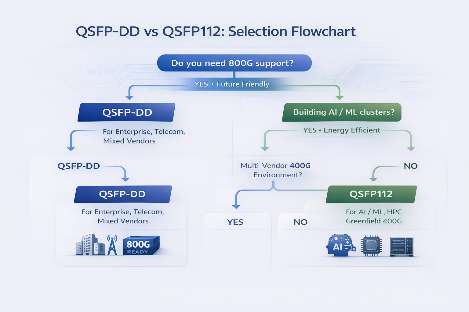
Choose QSFP-DD When:
Retrofitting BrownField Infrastructure:
When a company already has a 100G or 200G infrastructure in place, the family of QSFP-DD devices provides the best technology of the age. Being backward compatible with QSFP28 and QSFP56 modules, organizations can now carry out incremental upgrades rather than having to perform a forklift replacement operation.
Multi-Vendor Solutions:
Two factors make the QSFP-DD a compelling option for multi-vendor instances. One key reason is its vast ecosystem of partners that keep compatibility issues and/or intricacies at bay. The other is the ability to source switches from Cisco, Juniper, Arista, or Broadcom-based platforms with a guarantee of module compatibility.
Enterprise Data Center Deployments:
In a traditional enterprise data center situation with a bit of everything going, QSFP-DD appears to make good business sense owing to its eco-friendly profile and general vendor neutrality. From the long interconnect point-of-view, the ability to work with coherent optics (ZR/ZR+) might be more lucrative for corporations that are geographically displaced.
800G Roadmap/Hardware Requirements:
The sole viable choice before your organization, within a 3-5 year span, in terms of connectivity, is QSFP-DD, impending consumption of 800G. That is to say: QSFP-DD800 is the platform that maintains the entire infrastructure’s value without replacement—infrastructure substitution often cancels ROI.
Coherent Optics Requirements:
For deployments requiring 400G-ZR or ZR+ coherent optics for metro or long-haul connectivity, QSFP-DD is the dominant form factor. Learn more about QSFP-DD ZR coherent optics capabilities. Coherent QSFP112 modules are limited in availability and vendor support.
Choose QSFP112 When:
AI and Machine Learning (AI/ML) Training Clusters:
For GPU cluster service running for AI training, QSFP112 has made its claim as optimum connection technology. QSFP 112 refers to a footprint shared by NVIDIA’s ConnectX-7 adapters and Quantum-2 Switches for GPU-based networks.
Power Efficiency Prioritization:
QSFP112 stands with 15% to 25% power saving, so they create a significant difference in operational cost savings in case there is a need for constraint on one or both power and cooling capacity, which is becoming increasingly worse in the case of extremely high-density deployments or regions with very expensive electricity rates.
Greenfield 400G Deployments:
QSFP112, optimized explicitly for 400G performance, offers an all-new data center design with no emphasis on legacy infrastructure. It is a brand-new creation for the digital era with maximum efficiency and no baggage of backward compatibility to hold it back.
NVIDIA-Centric Infrastructures:
Companies that select NVIDIA GPU compute clusters and networking ought to migrate to the choices of form factor of NVIDIA. For NVIDIA networking, QSFP112 is considered an option. This choice ensures the optimal compatibility and performance.
High Performance Computing and Supercomputing:
Higher vested interests, especially those power-focused NVidia network induction might standardize with QSFP112 and HPS-built switch lineup with InfiniBand NDR (400G).
Decision Matrix by Scenario
| Deployment Scenario |
Recommended Form Factor |
Primary Rationale |
| Enterprise DC upgrade from 100G/200G |
QSFP-DD |
Backward compatibility |
| AI training cluster with NVIDIA GPUs |
QSFP112 |
Native NVIDIA support |
| Mixed vendor enterprise network |
QSFP-DD |
Broad ecosystem |
| 800G roadmap (3–5 year horizon) |
QSFP-DD |
Only 800G path |
| Power-constrained hyperscale deployment |
QSFP112 |
Efficiency advantage |
| Greenfield 400G only |
QSFP112 |
Optimized design |
| Coherent optics (ZR/ZR+) required |
QSFP-DD |
Broader coherent support |
| HPC/InfiniBand NDR |
QSFP112 |
HPC ecosystem |
Total Cost of Ownership Considerations
Beyond module pricing, consider these TCO factors when making your decision:
Infrastructure Longevity:
- •QSFP-DD: Protects switch investment through 800G upgrade cycle
- •QSFP112: May require switch replacement for 800G migration
Operational Costs:
- •QSFP-DD: Higher power and cooling costs over deployment lifetime
- •QSFP112: Lower ongoing operational expenses
Vendor Lock-In Risk:
- •QSFP-DD: Lower risk due to broad vendor ecosystem
- •QSFP112: Higher concentration risk, particularly for NVIDIA-centric deployments
Supply Chain Resilience:
- •QSFP-DD: Multiple vendor sources reduce supply risk
- •QSFP112: More concentrated supplier base
800G Roadmap and Future-Proofing
For organizations evaluating QSFP-DD800 vs QSFP112 for long-term infrastructure, understanding the 800G roadmap implications is critical.
QSFP-DD800: The 800G Upgrade Path
QSFP-DD800 represents the evolution of the QSFP-DD form factor to support 800 Gigabit Ethernet. It maintains the same 8-lane electrical architecture but doubles the per-lane speed to 100G PAM4.
QSFP-DD800 Technical Specifications:
- •Electrical Interface: 8 × 100G PAM4
- •Total Bandwidth: 800 Gbps
- •Form Factor: Identical to QSFP-DD (backward compatible cages)
- •Power Consumption: 15–18W typical
The key advantage is infrastructure investment protection. Organizations deploying QSFP-DD switches today can upgrade to 800G by simply swapping optical modules when 800G switch ASICs become available. Cables, cages, and switch hardware remain compatible.
Timeline Considerations:
- •800G switch ASICs (Broadcom Tomahawk 5) are sampling now
- •Production deployments expected 2026–2027
- •QSFP-DD800 modules are already available for early adopters
QSFP112 Limitations: No 800G Path
QSFP112 is fundamentally limited to 400G by its 4-lane architecture. Even at maximum 112G per lane, four lanes cannot deliver 800G without lane doubling.
Implications for QSFP112 Deployments:
- •No module upgrade path to 800G
- •800G migration requires switch hardware replacement
- •Form factor transition necessary for bandwidth growth beyond 400G
- •Plan for 3–5 year infrastructure lifecycle if 800G anticipated
Organizations choosing QSFP112 should do so with clear-eyed understanding that it represents a 400G-only solution. If 800G is likely within your infrastructure planning horizon, QSFP-DD provides better investment protection.
Alternative: OSFP for Maximum Future-Proofing
For organizations wanting maximum future-proofing beyond 800G, OSFP (Octal Small Form-factor Pluggable) offers an alternative path.
OSFP Advantages:
- •Supports 800G today (8 × 100G)
- •Roadmapped to 1.6T (OSFP1600) using same cage
- •Superior thermal management for high-power optics
- •Growing ecosystem support
OSFP Tradeoffs:
- •No backward compatibility with QSFP modules
- •Requires complete infrastructure replacement
- •Different physical form factor (larger than QSFP)
For greenfield deployments with 10-year infrastructure horizons, OSFP may warrant consideration alongside QSFP-DD and QSFP112.
Conclusion
The QSFP-DD vs QSFP112 comparison just outlined just explains why selection either of those optically-based solutions is entirely down on usage intention, infrastructure in place, future bandwidth necessities-it’s not one size fits all. Each form factor triumphs in different cases.
Key takeaways for your decision process:
QSFP-DD provides the most flexible upgrade path with backward compatibility to 100G/200G and forward compatibility to 800G via QSFP-DD800. Choose it for brownfield upgrades, multi-vendor environments, and when 800G is in your roadmap.
QSFP112 delivers superior power efficiency and is the form factor of choice for AI/ML clusters, particularly those built around NVIDIA infrastructure. Choose it for greenfield 400G deployments where power efficiency matters more than upgrade flexibility.
Never assume compatibility based on physical fit alone. Always verify electrical interface support in your switch datasheets before procurement.
Consider TCO over 5-year horizons, including not just module costs but power consumption, cooling requirements, and future upgrade paths.
As 400G becomes the standard for data center spine layers and AI cluster fabrics, understanding these form factor distinctions enables infrastructure decisions that balance immediate requirements with long-term scalability. For assistance selecting the optimal form factor, explore our QSFP-DD optical modules or contact our optical networking engineers to discuss your requirements.
Frequently Asked Questions
Q: Can I put a QSFP112 module in a QSFP-DD port?
The module fits physically, but it will only work electrically if the switch ASIC specifically supports 112G electrical signaling. Most QSFP-DD breakouts are designed with 50G electrical lanes, which are incompatible with QSFP112 modules. Before you insert a module into such a switch, check that the port is compatible with QSFP112.
Q: Is QSFP112 backward compatible with QSFP28 (100G) modules?
QSFP112 port will only take a QSFP28 module if the switch is set for 25G electrical lanes or has liaison speed negotiation capabilities. Modern-day switches that are optimized for the QSFP112 module, especially in AI/ML workload scenarios, are set to operate at 400G only. To check for compatibility information on your specified switch, please refer to the switch’s data sheet.
Q: Which form factor is more power efficient?
QSFP112 is 15-25% more power-efficient than QSFP-DD. In the QSFP-DD form factor, a typical 400G SR4 module consumes an average of 10W compared to 8W in the case of QSFP112 modules. This difference matters very much when the volume is pushed up to significant operational savings and minimized cooling requirement.
Q: Can I upgrade the QSFP112 to 800G in the future?
No, it is not possible. The 4-lane architecture of the QSFP112 is outshone by the 400G only. There is no upgrade path to an 800G without replacing the switch hardware and jumping to a different form factor (either QSFP-DD or OSFP).
Q: Do Cisco switches support QSFP112?
Mostly it is the QSFP-DD due to enterprise and service provider Cisco switches that support QSFP-DD rather QSFP112. QSFP112 devices are rather somewhat limited to selected platforms focusing on AI/ML workloads in the Cisco ecosystem. Please check each switch model’s datasheet for the available form factors.
Q: Why does NVIDIA use QSFP112 instead of QSFP-DD?
According to NVIDIA, its networking portfolio (ConnectX-7, Quantum-2) has been tailored for power efficiency and signal integrity characteristics that are relevant to a 4-lane architecture connecting QSFP112. For GPU clusters that need to manage power, the best option offered by QSFP112 is the power benefit versus flexibility associated with QSFP-DD.
Post Views: 39