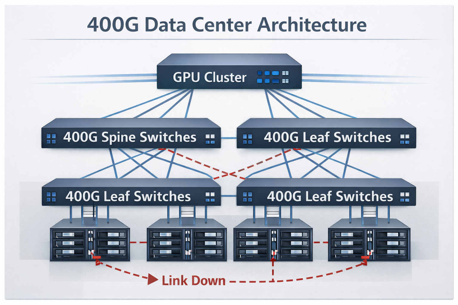
Just at 2:47 AM on a Tuesday; the alerts came gushing in. 48 hours before, the new 400G spine switches came live. At present, on their first sparely deployed 16 QSFP-DD infrastructure; the major hyper-scaler data center engineers were frantically looking at dashboards showing 23 link down events. The time span of the down time stood before them. Here were frantic minutes: thousands of dollars will be lost in about every minute of downtime and on top of that, some angry customer matters. The cause? It so happened that all the defaults in the CMIS 4.0 compatibility and contaminated MPO-16 connectors escaped the scope of the standard 100G troubleshooting playbook.
Such issues are seen more frequently as network operators race to deploy 400G infrastructure at a screaming pace. QSFP-DD troubleshooting presents unique challenges where no other optical generation, despite SERDES/Line interfaces, has posed before. Network engineers look into dedicated snags beyond standard optical transceiver failure modes when QSFP-DD link down trouble arises. Enforcement of PAM-4 modulation, instantaneously with FEC requirements, and that shall come over the CMIS management interface, spawns fail modes to be diagnosed through new diagnostic ways; knowledge of the pertinent commands of the “platform” is good.
This guide provides a comprehensive framework for QSFP-DD troubleshooting and 400g transceiver troubleshooting. You will learn systematic diagnostic methodologies, platform-specific optical transceiver diagnostic commands for Cisco, Juniper, Arista, and NVIDIA switches, QSFP-DD ddm alarms interpretation, FEC error analysis, and predictive maintenance strategies that prevent failures before they impact production traffic. For an overview of available module types, see our comprehensive QSFP-DD guide.
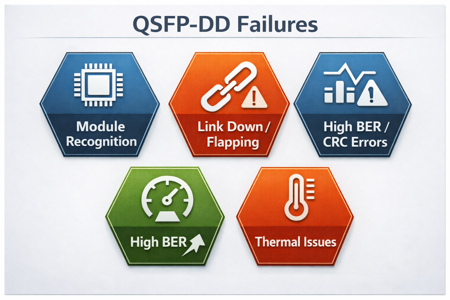
Common QSFP-DD Failure Modes in 400G Networks
The identification of the root reasons behind failure events occurring in QSFP-DD systems and modules allows for faster diagnosis and quicker resolution of issues. Electrical signaling, optical transmission, and management interfaces tend to combine mainly to produce a variety of failure categories that are distinct from those seen in previous transceiver generations.
Module Recognition Failures
If a QSFP-DD module does not appear in the inventory of the switch, it mostly indicates one of the three issues, namely CMIS’ non-compliance, unable to authenticate vendor, or power initialization issues.
CMIS 4.0 EEPROM Decoding Errors
The EEPROM memory map of modern QSFP-DD modules follows CMIS 4.0 as specified by the QSFP-DD MSA. This introduces variable offsets compared to earlier standards, causing switch firmware with hardcoded assumptions (common in older revisions) to misread vendor identification or fail to decode the module entirely.
Logs may show “unsupported transceiver” or CMIS decode failure errors. The module might appear in inventory as a generic or unknown type (as in the Tuesday scenario), with incorrect or missing manufacturer details. This issue is especially common on SONiC-based switches and older firmware of traditional network operating systems.
The resolution is to update firmware for full CMIS 4.0 support with variable offset handling, or to use modules that maintain backward compatibility with CMIS 3.0 and earlier management interfaces.
Creation of vendor lock-in policy
Many vendors on their switch implement EEPROM validation that rejects third-party optic modules. The switch logs error messages like “%SFP-4-UNSUPPORTED_SENSE.” The switch has recognized via logs accessed from syslog that the module is not an OEM and, therefore, is blocked from initializing.
Different switch platforms may offer a global configuration option such as “service unsupported-transceiver” in Cisco to override such rules, potentially risking warranty terms. Similar protections exist on Juniper and Arista devices, which may require manual third-party enablement or modules with properly coded vendor and compliance information.
Mismatch of Power Classes
As far as power provided through a QSFP-DD module goes, it is rated to a power class of up to 8 Watts for high-band coherent optic transceiver applications. In practice, if the platform provides less power availability or the QSFP module declares a higher power class, the module will init fail with no warning messages or with power-fail alarms.
Link Down and Link Flapping
The most visible QSFP-DD link down failures exhibit links that never establish or hang between up and down states in continuous flapping. These failures are physical in nature for the most part or may owe existence to feasible configuration mismatches or optical power issues.
Physical Layer Problems
About 400G DR4 and other parallel optic link failures result from connector contamination in a significant portion of cases (often 65-70%). QSFP-DD applications commonly use MPO-16 or MPO-12 connectors with Angled Physical Contact (APC) polish to ensure proper optical return loss performance for PAM-4 signaling. Any contamination, damage, or improper cleaning can generate reflections that PAM-4 modulation tolerates poorly.
Module seating issues are also important factors to be considered in terms of link failures. Proper engagement of the QSFP-DD module in the connector cage requires the module to be inserted fully until the retention latch audibly clicks. Partial insertion can cause intermittent contact at high-speed signal pins and result in errors on specific lanes or complete link shutdown.
FEC Configuration Mismatches
In comparison to 100G networks, where FEC could sometimes be optional, 400G Ethernet makes RS-FEC (Reed-Solomon) mandatory in most applications. RS(544,514)—also known as KP4 FEC—is the standard for 400GBase-SR8, DR4, FR4, and LR4 modules.
Having mismatched FEC configurations at each end of the link will impede link establishment or raise error rates above acceptable thresholds. Common issues include one end with FEC enabled and the other disabled, different FEC types (RS-FEC vs FC-FEC), or incorrect handling on breakout cables that expect host-side FEC termination.
Optical Power Concerns
QSFP-DD receivers have a relatively narrow operating window. When received power drops below the sensitivity threshold, RX-LOS alarms trigger; when it exceeds the overload limit, the detector saturates and distorts the signal.
For 400G-SR8 modules, typical receiver sensitivity is around -8.4 to -8.5 dBm (per lane, average power, informative) with overload at +4 dBm. DR4 and FR4 modules often provide sensitivity down to approximately -5.9 to -7 dBm or better depending on implementation, offering less overall optical budget margin. Long-reach modules require careful consideration of fiber loss, connector loss, splices, and aging margins.
High BER and CRC Errors
In spite of a successful link establishment, bit errors remain noteworthy to QSFP-DD modules with the potential to thwart application operation or trigger protective link shutdowns.
Pre-FEC vs Post-FEC Error Analysis
At a speed of 400G, background bit errors are common and expected. The RS-FEC will correct up to 15 symbols per 544 symbol codewords. Acceptable pre-FEC bit error rates exceed rather under 2.4×10⁻⁴ of operation, meanwhile post-FEC should be kept below 1×10⁻¹². 885/1000.
When pre-FEC errors exceed thresholds, or post-FEC errors appear, understanding shall validate whether these errors are coming from the signal integrity impairments, optical degradation, or defects in the hardware.
Signal PAM-4 Degradation
The PAM-4 modulation used in 400G QSFP-DD carries two bits per symbol across four voltage levels, making it significantly more sensitive to noise, crosstalk, and voltage displacement than NRZ used in 100G. Eye diagram analysis or DSP-reported error statistics help detect degraded margins caused by lane crosstalk or power supply noise.
Lane-Specific Errors
The QSFP-DD module exposes 8 electrical lanes to the host, each operating at 53.125 Gbaud with PAM-4 encoding. Individual lane faults manifest as specific error patterns or capacity reduction. Troubleshooting should determine whether the issue originates from the host ASIC, the electrical interface to the module, or individual optical channels.
Thermal Issues and Temperature Alarms
QSFP-DD modules dissipate significant heat, with power consumption ranging from 10W for short-reach modules to 25W for coherent ZR+ optics. Understanding QSFP-DD power consumption characteristics helps diagnose thermal-related failures. Thermal management directly impacts reliability and performance.
Temperature Limits
CMIS-compliant modules report temperature via DDM. For commercial-grade modules, the normal operating range is typically 0 to 70°C. Warning thresholds often trigger at 70-75°C, with critical alarms at 80-85°C. Above 85°C, modules may shut down lasers or reduce output power to prevent damage.
High temperatures accelerate laser aging, increase bias current, and can cause thermal throttling that reduces link margin and elevates error rates.
Cooling and Airflow
Thermal planning is a necessity for high-density 400G switch deployments. Ensure front-to-back airflow is not disrupted by cables. Ambient temperature at the switch intake should not exceed 45°C. Stacking without ventilation gaps or blocking fan trays creates hot spots that trigger module temperature alarms.
QSFP-DD Troubleshooting: Diagnostic Commands by Platform
A proper QSFP-DD troubleshooting solution will require some deep knowledge of diagnostic commands specific to the platform on which you are working. Different command hierarchies and syntax schemes, therefore, are provided by each network operating system.
Cisco IOS-XR and NX-OS
Cisco platforms provide comprehensive optical diagnostics through the show controllers command family.
Basic Transceiver Information
show interfaces FourHundredGigE x/y/z transceiver detail
show controllers optics x/y/z
These commands display module identification, DDM readings, alarm status, and optical power levels. The transceiver detail output includes vendor information, part numbers, serial numbers, and real-time optical parameters.
FEC Diagnostics
show fec event-log interface FourHundredGigE x/y/z
show controllers HundredGigE|FourHundredGigE x/y/z phy
FEC event logs track corrected and uncorrected codeword statistics. High rates of corrected errors indicate marginal signal quality, while uncorrected errors indicate link failure. PHY-level diagnostics expose PCS (Physical Coding Sublayer) error counters and lane alignment status.
Coherent Optics Diagnostics
For 400G-ZR and ZR+ modules, special diagnostic commands expose DSP telemetry. Learn more about coherent optics specifications in our QSFP-DD ZR coherent optics guide:
show controller coherentDSP x/y/z
This command exposes DSP-reported statistics including pre-FEC BER, post-FEC BER, OSNR (Optical Signal-to-Noise Ratio), chromatic dispersion compensation, and polarization mode dispersion tracking.
Juniper JunOS
Juniper platforms organize optical diagnostics under interface-specific show commands.
Optical Diagnostics
show interfaces diagnostics optics et-x/y/z
show interfaces et-x/y/z extensive | match “fec\|error\|alarm”
The extensive interface output includes FEC statistics, error counters, and alarm flags in a structured format suitable for automated parsing.
FPC-Level Diagnostics
For deeper inspection on PTX series routers:
request pfe execute target fpc0 command “show qsfpdd x/y/z”
This command accesses the Packet Forwarding Engine’s view of the QSFP-DD module, exposing low-level register values and hardware status.
Chassis Hardware Inventory
show chassis hardware
show system alarms
These commands identify unrecognized modules, hardware faults, and system-level alarms that may affect multiple interfaces.
Arista EOS
Arista EOS provides straightforward command structures for optical diagnostics.
Transceiver Information
show interfaces Ethernetx/y transceiver
show interfaces Ethernetx/y phy detail
The transceiver command shows identification and DDM data. PHY detail exposes signal integrity metrics and FEC counters.
Error Monitoring
show interfaces Ethernetx/y counters errors
This command displays CRC errors, symbol errors, and other Layer 1 statistics that indicate signal quality problems.
Environmental Monitoring
show system environment temperature
Track thermal conditions affecting module performance. Arista switches report both intake temperature and individual sensor readings.
Port Channel FEC Status
show port-channel x detailed | grep -i fec
For aggregated links, verify FEC consistency across all member ports.
NVIDIA Cumulus Linux
Cumulus Linux exposes QSFP-DD diagnostics through standard Linux tools and platform-specific commands.
EEPROM Reading
ethtool -m <interface>
ethtool -m <interface> raw on
The ethtool command reads transceiver EEPROM contents including identification and DDM thresholds. Raw mode displays hex dumps for advanced troubleshooting.
SONiC-Specific Commands
show interface transc eeprom
show interface transc status
SONiC-based switches provide transceiver-specific show commands that decode CMIS registers and expose management interface data.
Module Reset Procedures
For unresponsive modules on specific platforms:
# T3048-LY9 example
sudo echo 0 > /sys/class/gpio/qsfpd_power_enable/value
sudo rmmod quanta_ly9_rangeley_platform
sudo modprobe quanta_ly9_rangeley_platform
sudo systemctl restart switchd.service
These commands cycle power to the QSFP-DD cage and reload platform drivers.
QSFP-DD DDM Alarms: Monitoring and Interpretation
Digital Diagnostic Monitoring (DDM) provides real-time visibility into transceiver health. The SFF-8472 specification and CMIS standards define standardized parameters that enable predictive maintenance and rapid fault isolation.
Critical DDM Parameters
Five crucial QSFP-DD module monitoring health parameters are temperature, supply voltage, TX bias current, TX optical power, and RX optical power.
Fan signals, J2, and MDIO offer temperature or die temperature for monitoring. The data sheet of the respective module type will reveal how optical performance may change with temperature. Commercial grade modules mainly operate from 0oC to 70oC whereas the industrial grade options are specified for operation at -40oC to 85oC.
Rising temperatures mean cooler problems or ambient conditions becoming quite warm. Whenever the temperature reaches above 70oC, our warning threshold will intervene as it actively eats away the module’s lifespan.
For troubleshooting temperature critical alarms seeking proof, make sure fans, chassis, and air filters are doing their jobs vigorously, as well as insisting on airflow fixture across the length of the chassis to maintain the air cycle cool. More attention needs to give a high-density installation where 400G switching option staring in the face of the other amidst the great number of optic components.
Current on TX Bias
Laser bias current is an indicator of the health of the transmitter. Depending on the module type, the normal values range from 20 mA to 80 mA. When the bias current rises, the laser ages and this is typically the first sign of impending end-of-life failure. A laser’s biasing current above 100 mA usually suggests that the laser will need to be replaced within weeks.
A sudden drop in the bias current, approaching near-zero levels, is indicative of a failure of the driver circuit or laser diode damage. These have generally resulted in module replacement in the past.
Optical Power is quite important, where TX power shows transmitter output and RX power shows received signal strength. The interfacing of both elements is vital to the reliability of link operations.
With a power range from -2.4 dBm to +4 dBm per lane, the TX power of the 400G-SR8 modules lies between this parameter. RX power should, by DDM specification requirements, fall between -8 dBm and +4 dBm. Near-zero values such as 0.0000 and 0.0001 mW from DDM outputs generally imply no signal input received or that DDM is not used.
In optical communication, energy above the noise level typically causes transmission errors. Besides, energy below the receiver’s sensitivity also disrupts transmission. Above the detector saturation energy level, the optical receiver may also produce bit errors due to the mixing of telemetry frequencies. Customer definitions of acceptable link health and power level difference indicate quantifiable specifications for optical transceivers.
Supply Voltage Monitor
When the product is in active mode,the nominal value of the Vcc is 3.3V, with an operating range of 3.13-3.47V. Deviations indicate power supply-related problems or internal regulation failures within the module and are among “expected-to-be” characteristics.
Alarm Threshold Hierarchy
Every parameter has four levels of limits to look out for, such as high-alarm, high-warning, low-warning and low-alarm limits. Having said so, prioritization for reply may be appropriately exercised.
Warning States Versus Alarm States
A warning state is displayed for all levels and all parameters when the parameter stands outside the high-water mark but within the lower ceiling. This leads to safety threats that are due to casual degradation in the parameter. At this point, action could be deferred until a maintenance outage. But once the warning attendant turns into the alarm categorization, it is a totally different dimension.
Warnings for low power show a beautifully degrading plant or dirty connectors. Low RX power alarms have may predict imminent link failure. Based on this, one may consider informing the network operations team well in advance or starting with the brieffng of whoever contacts eminent response.
Predictive Failure Indicators
Trending DDM data enables predictive maintenance that prevents unexpected failures:
- •Rising bias current trending toward warning thresholds indicates laser aging. Schedule replacement before failure.
- •Gradually decreasing RX power suggests fiber degradation or connector contamination. Clean and inspect before link failure.
- •Increasing temperature trends indicate cooling system degradation. Address before thermal shutdown.
Research indicates 60-70% of optical module failures become predictable 30-90 days in advance through DDM trend analysis.
DDM Decision Tree
When DDM alarms appear, follow a systematic diagnostic sequence:
1. Identify the parameter triggering the alarm– Temperature, voltage, bias current, or optical power
2. Check correlated parameters– Temperature and bias current often rise together; voltage problems affect multiple modules
3. Determine if sudden change or gradual degradation– Sudden changes suggest hardware failures; gradual trends indicate aging
4. Isolate the fault domain– Single module failures point to module defects; multiple module alarms suggest chassis-level issues
5. Take corrective action– Clean connectors, improve cooling, replace modules, or repair fiber plant as indicated
QSFP-DD FEC Errors: Troubleshooting Guide
Forward Error Correction is mandatory for 400G operation, making FEC analysis essential for QSFP-DD troubleshooting.
Understanding RS-FEC at 400G
400G Ethernet uses RS-FEC with RS(544,514) coding as defined in IEEE 802.3bs, also known as KP4 FEC. This implementation adds 30 parity symbols to each 514-symbol data payload, enabling correction of up to 15 symbol errors per codeword.
The pre-FEC and post-FEC BER
Pre-FEC BER should remain below 2.4×10⁻⁴ to ensure proper RS-FEC operation, while post-FEC should remain below 1×10⁻¹².
Normal operation at speeds of 400G suggests low pre-FEC error rates; this situation sees the background errors present up to the FEC level in a transparent manner. Otherwise, when the pre-FEC rates consistently reach the thresholds or results in post-FEC errors, it becomes a matter of concern.
Latency issues
The latency incurred in the encoding and decoding of FEC is very minute, about 100 ns. These 100 ns quite often go unnoticed in many application layers but can be made more pronounced in ultra-low-latency environments like financial trading networks.
FEC Mismatch Issues
Configuration Verification
Both ends of a 400G link must use matching FEC configurations. Common mismatch scenarios include:
- •One end with RS-FEC enabled, the other disabled
- •RS-FEC vs FC-FEC type mismatches
- •Host-side FEC vs module-internal FEC conflicts
On Cisco platforms, verify FEC status with show fec event-log. On Juniper, check show interfaces extensive output. Arista exposes FEC counters in show interfaces counters errors.
Breakout Cable FEC Termination
FEC handling in a configuration of 400GFlexE/OTUCN to 4x100G is crucial since the FEC for the 400G port is RS-FEC(544,514) while the 100G breakout port employs either KR4 FEC or no FEC depending on configuration. Wrong termination in one port can result in FEC errors in the QSFP-DDs that are hard to enumerate without proper testing equipment.
The FEC in the breakout point should be properly terminated. Some equipment will do the FEC conversion in the ASIC, but others require an explicit configuration. When these standards clash, there will be the possibility of link failures and tens of error rate counts within the breakout ports.
Error Pattern Analysis
Monotonic vs. Non-Monotonic Distributions
One expects healthy FEC error distributions to show a monotonic decrease as the symbol error count increases. According to the theory of statistics, the error counts should smoothly decrease by a power of about ten with each additional symbol error per codeword.
Non-monotonic distributions with isolated peaks or irregular patterns suggest systematic issues with the system. Errors due to DSP firmware bugs, clock recovery issues, or crosstalk create unique error signatures that differ significantly from a more statistically observable outcome.
Burst Errors vs. Random Errors
Normally, single-bit errors are randomly distributed and, hence, are well corrected. A burst error is likely to indicate multiple consecutive bit errors and, as such, signal integrity problems, timing violations, or hard-fault issues.
Bit Slips
Bit slips happen when the receiver sampling points are displaced in orientation to the data stream received. This situation is different from random errors in descant corrections: bit slips happen when an unexpected spike manifests itself and are not corrected by FEC. Bit slips may point to CDR trouble, reference clock instabilities, or FIFO overflow conditions.
400G Transceiver Troubleshooting: Physical Layer Issues
Physical layer issues cause the majority of QSFP-DD failures. Systematic inspection of connectors, fiber, and module installation prevents many common problems.
MPO-16 Connector Cleaning and Inspection
400G QSFP-DD modules using SR8, SR4, DR4, or similar parallel optics require MPO-16 or MPO-12 connectors with APC polish. Proper cleaning and inspection is critical.
Inspection Procedures
Use a fiber inspection microscope with 400x magnification to examine connector end-faces. Look for:
- •Dust and debris particles
- •Oil and contamination films
- •Scratches and pitting
- •Proper APC angle alignment
Reject connectors showing significant defects or contamination that cleaning cannot resolve.
Cleaning Techniques
Use lint-free wipes and appropriate solvent for dry cleaning. For APC connectors, ensure cleaning tools match the 8-degree angled polish. Improper cleaning tools damage APC end-faces.
Wet-to-dry cleaning often produces best results: apply small amount of solvent to wipe, clean connector, then dry with fresh wipe. Inspect after cleaning to verify effectiveness.
MPO Polarity Verification
Parallel optic applications require correct MPO polarity. Method B (crossover) is standard for most 400G applications. Verify polarity with a visual fault locator or MPO polarity tester before installation.
Module Installation Best Practices
Unseating Verification
In order for QSFP-DD modules to seat properly, one must insert them forcefully until the latch locks with a click, if one stops short, high-speed lane connections may not function properly, thus making errors arduous to diagnose.
When experiencing intermittent connectivity, module problems, or lane-specific errors, check if they can be pushed to their positions without forced alignment.
Golden Finger Inspection
Before inserting a module, check its electrical contacts (golden fingers) for contamination, corrosion, or mechanical damage. Clean them using the appropriate contact cleaner if necessary.
The same should be done for the switch cage contacts. If broken or unhealthy anymore, they might simply need a broken switch to be replaced or repaired with new ones.
Cable Strain Relief
MPO and DAC cables may be heavy and stiff. Design enough strain relief to prevent any damage to cage or module that may occur due to pulling a connector out. Minimize sharp cable bends that exceed the minimum bend radius specifications.
Fiber Plant Troubleshooting
Link Budget Verification
Calculate total link loss including fiber attenuation, connector loss, and splices. Compare against module specifications:
| Module Type |
Max Loss Budget
|
Typical Distance
|
| 400G-SR8 |
~1.9-2.0 dB
|
100m (OM4)
|
| 400G-DR4 |
~3-6 dB
|
500m (SMF)
|
| 400G-FR4 |
~4-8 dB
|
2 km (SMF)
|
| 400G-LR4 |
~6-10 dB
|
10 km (SMF)
|
Excessive loss indicates fiber degradation, macrobends, or dirty connectors. Use an optical power meter to measure actual loss and an OTDR to locate high-loss events.
Single-Mode vs Multi-Mode Verification
Verify fiber type matches module requirements. Connecting single-mode modules to multi-mode fiber causes high loss and mode dispersion. Multi-mode modules on single-mode fiber may appear to work but with severely limited distance.
Breakout Cable Specific Issues
400G to 4x100G breakout configurations introduce additional troubleshooting complexity beyond standard point-to-point links. For comprehensive guidance on breakout deployments, refer to our QSFP-DD breakout cable guide covering lane mapping, MPO polarity, and deployment scenarios.
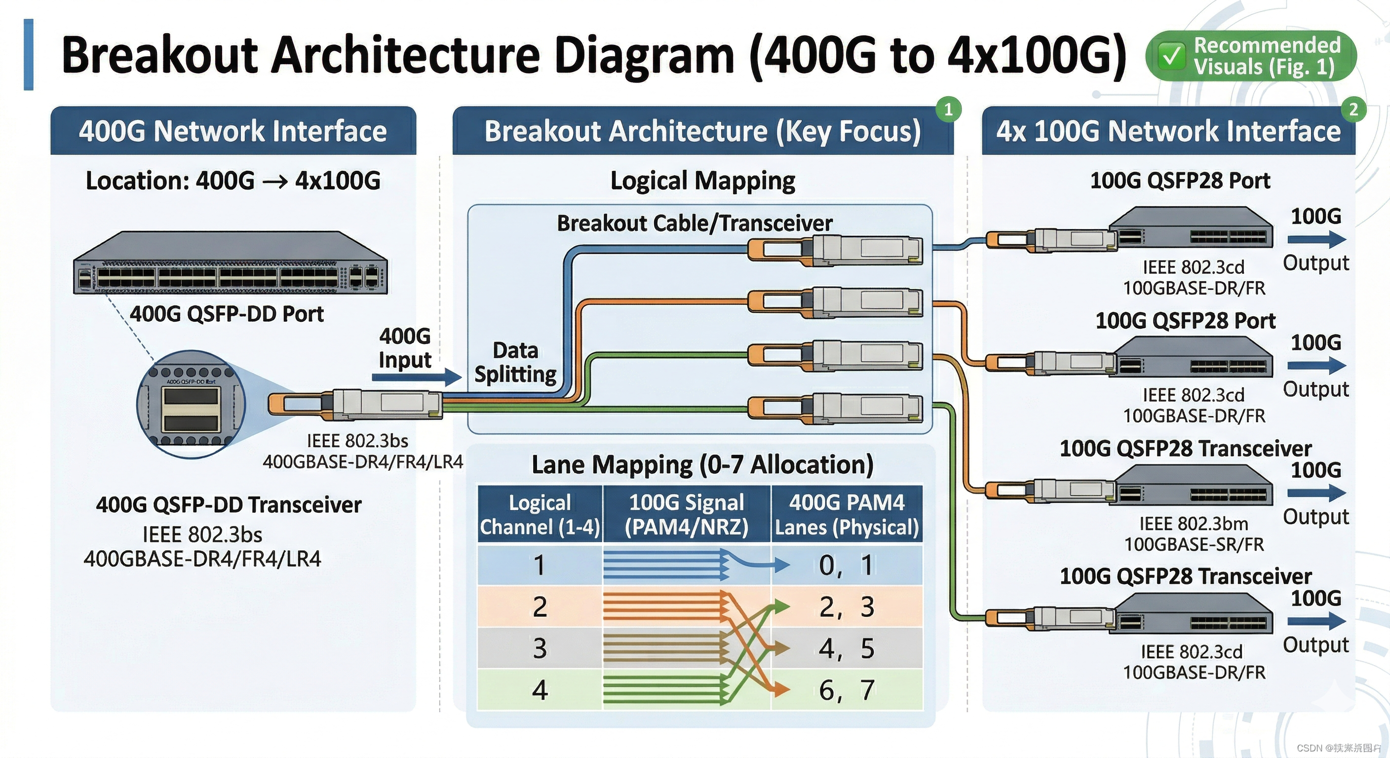
Lane Mapping Errors
QSFP-DD modules expose 8 electrical lanes to the host. In breakout mode, these lanes map to four independent 100G ports, each using two lanes (CAUI-4 interface).
Configuration Verification
Verify switch configuration matches breakout cable type. Incorrect lane mapping causes some breakout ports to fail while others work. Common mappings include:
- •400G to 4x100G: Lanes 0-1 → Port 1, Lanes 2-3 → Port 2, etc.
- •400G to 2x200G: Lanes 0-3 → Port 1, Lanes 4-7 → Port 2
Switch ASIC and firmware must support the desired breakout configuration. Not all platforms support all breakout modes.
Individual Lane Troubleshooting
When some breakout ports work and others fail, isolate whether the problem is:
- •Electrical lane issues between switch ASIC and module
- •Optical lane problems within the module
- •Individual fiber channel problems in the breakout cable
DDM readings on the 400G module may show per-lane optical power levels. Uneven power levels between lanes indicate module problems or fiber damage.
MPO Polarity for Breakouts
Breakout cables use internal fiber “shuffles” to map MPO connector lanes to individual duplex LC or MPO connectors. Incorrect polarity causes transmit-to-transmit or receive-to-receive connections that fail to establish link.
Polarity Method B (Crossover)
Method B uses a single crossover in the cable to ensure proper TX-to-RX mapping. For breakout cables, this means:
- •MPO pin 1 → LC connector A TX
- •MPO pin 2 → LC connector A RX
- •MPO pin 3 → LC connector B TX
- •MPO pin 4 → LC connector B RX
Verify polarity with a visual fault locator before installation. Light transmitted on the TX fiber should appear at the far end RX fiber.
Predictive Maintenance Strategies
DDM trend analysis enables proactive maintenance that prevents unexpected failures and reduces downtime.
Laser End-of-Life Prediction
Laser diodes degrade gradually, showing characteristic DDM signatures before failure:
- •Early stage: Slight bias current increase (5-10% above baseline)
- •Mid stage: Noticeable bias current rise (15-25% above baseline) with possible temperature increase
- •Late stage: Significant bias current elevation (>30% above baseline), decreasing TX power, elevated temperature
- •Failure: Bias current exceeds maximum or drops to near-zero (catastrophic failure)
Schedule replacement when bias current trends exceed 20% above initial baseline. This typically provides 2-4 weeks advance notice before failure.
Fiber Plant Degradation Detection
Gradual RX power decrease indicates fiber degradation:
- •Connector contamination accumulating over time
- •Fiber microbends from cable movement or stress
- •Aging splices developing higher loss
Trending RX power decrease of more than 1 dB from initial installation values warrants inspection and cleaning. More rapid decreases indicate acute problems requiring immediate attention.
Temperature Trend Analysis
Increasing temperature trends indicate:
- •Cooling system degradation (fan failure, filter clogging)
- •Increasing module power consumption (aging components)
- •Environmental changes (seasonal temperature shifts, HVAC problems)
Temperature increases of more than 5°C from baseline trigger investigation. Sustained temperatures above 70°C significantly accelerate component aging.
Automated Monitoring Implementation
Polling Strategy
Critical 400G links benefit from frequent DDM polling:
- •Critical production links: 30-60 second intervals
- •Standard infrastructure: 5-10 minute intervals
- •Monitoring links: 15-30 minute intervals
Alert Threshold Configuration
Configure monitoring systems to alert on:
- •Any alarm flag conditions (immediate response)
- •Warning flag conditions persisting >15 minutes (scheduled maintenance)
- •Parameter trends approaching warning thresholds (predictive)
- •Rapid parameter changes indicating acute failures (emergency)
Systematic Troubleshooting Workflow
A structured approach to QSFP-DD troubleshooting minimizes diagnostic time and ensures comprehensive fault isolation.
Phase 1: Physical Verification
Begin every troubleshooting session with physical inspection:
- •Visual inspection: Check module seating, connector engagement, cable condition
- •Connector cleaning: Clean and inspect all optical connectors even if they appear clean
- •Seating verification: Remove and reinstall modules to ensure proper engagement
- •Cable verification: Confirm correct cable type, polarity, and routing
Approximately 40% of QSFP-DD problems resolve during physical verification phase.
Phase 2: DDM Analysis
If physical verification does not resolve the issue:
- •Read DDM parameters for all relevant modules
- •Check alarm flags for temperature, voltage, bias current, optical power
- •Compare TX/RX power levels against specifications
- •Identify trends indicating degradation vs acute failure
- •Correlate alarms across multiple modules to isolate chassis-level issues
Phase 3: Configuration Verification
Verify switch and module configuration:
- •Confirm module recognition in switch inventory
- •Check port speed configuration matches module capability
- •Verify FEC configuration consistency across the link
- •Validate breakout configuration if applicable
- •Review recent configuration changes that might correlate with problem onset
Phase 4: BER and FEC Analysis
For links showing errors but remaining operational:
- •Check pre-FEC BER against thresholds
- •Monitor post-FEC errors indicating uncorrectable problems
- •Analyze error patterns for systematic issues vs random noise
- •Perform stress testing under heavy traffic loads
- •Compare error rates with baseline measurements
Phase 5: Isolation Testing
When fault domain remains unclear:
- •Swap test: Replace suspect module with known-good unit
- •Port test: Move module to different switch port
- •Cable test: Replace patch cables with known-good spares
- •Loopback test: Use loopback modules to isolate host from fiber issues
- •End-to-end substitution: Temporarily relocate equipment to known-good infrastructure
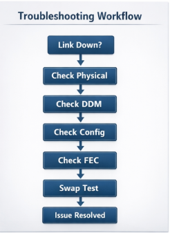
Quick Reference Decision Tree
Link Down Flow
- •Check physical layer (seating, connectors, cleaning)
- •Verify module recognition and DDM readings
- •Confirm FEC and speed configuration match
- •Measure optical power levels
- •Swap test with known-good module
High Errors Flow
- •Check pre-FEC BER and FEC error counters
- •Verify DDM temperature and power levels
- •Inspect fiber plant for damage or bends
- •Analyze error pattern (random vs systematic)
- •Consider module replacement if errors persist
Intermittent Issues Flow
- Monitor DDM trends over time
- Check for temperature correlation
- Verify connector stability under vibration
- Review logs for pattern correlation
- Implement continuous monitoring for capture
Conclusion
A systematic methodology must be applied while troubleshooting the QSFP-DD to take into consideration the unique characteristics of the 400G optical networking. Mandatory FEC, CMIS management interface, PAM-4 modulation, MPO high-density connectors-i.e., fundamentally different failure modes from earlier-are the result.
Key takeaways for effective QSFP-DD troubleshooting include:
- •Physical layer first: 70% of failures stem from connector contamination or improper module seating
- •Understand FEC: Normal operation includes correctable errors; focus on pre-FEC trends and post-FEC presence
- •Use DDM proactively: Trending data enables predictive maintenance that prevents unexpected failures
- •Know your platform: Diagnostic commands vary significantly between Cisco, Juniper, Arista, and NVIDIA switches
- •Verify breakout configurations: Lane mapping and polarity errors are common in 400G to 100G breakout deployments
As 400G and 800G networks become standard infrastructure, mastering these troubleshooting techniques becomes essential for network operations teams. The investment in systematic diagnostic procedures and monitoring automation pays dividends through reduced mean-time-to-repair and improved network availability.
For complex QSFP-DD troubleshooting scenarios or assistance with 400G deployment planning, contact our optical networking engineers. We provide technical support, compatibility testing, and diagnostic services to ensure reliable high-speed network operation. Explore our QSFP-DD optical modules to find compatible solutions for your infrastructure.
Frequently Asked Questions (FAQs)
Q1: What is the main cause of QSFP-DD link failures?
Connector contamination is attributed to roughly 65%-70% of all 400G link failures, especially involving DR4 and parallel optic modules. Before installing MPO-16 connectors, make sure they are meticulously cleaned and inspected. Inspect the connectors using a fiber microscope and clean them using the proper techniques, even if they seem visually clean.
Q2: How do I know if my switch supports a specific QSFP-DD module?
A: Check the switch vendor’s hardware compatibility list (HCL) for your specific model and firmware version. Our guide to QSFP-DD compatible switches lists the major platforms and their capabilities. Verify for CMIS version compatibility—older firmware may not recognize properly CMIS 4.0 modules. Update to the latest firmware that is recommended before addressing recognition issues.
Q3: Why does my QSFP-DD module work in one switch but fails to work in another switch?
Vendor lock-in settings can forbid third-party modules from proper access to some platforms. This can be noticed in system logs through numerical code messages labeled “transceiver unsupported.” Some of the switches might have a power class range limit. Difference in firmware can obstruct interoperability as well as the lack of feature support on a module that is not supported in one or more switches
Q4: How can I troubleshoot 400G to 4x100G breakout problems?
Verify that the switch ASIC and firmware support the breakout mode you are using. Check whether the lane mapping configuration matches the breakout cable type. Ensure that the MPO polarity is correct for breakout applications, usually defined as Method B. Test the single breakout ports for a fault. For an entire manual on deployment best practices for your QSFP-DD breakout cable, visit this page.
Q5: What do DDM trends indicate a replacement of the transceiver module?
Upon reaching 20% over their baseline, the increasing laser bias current represents the direction to end of life. Falling TX power along with the increase in the bias current confirms the fact; the laser has started deteriorating. Temperature trends going above ranges without any environmental factors signal an internal unit issue. Plan to replace the module if any of these trends are observed in any parameter getting close to the warning threshold.
Q6: Keeping aside other considerations, is KP4 (RS-FEC [544,514]) better for [400G QSFP-DD]?
400GBase-SR8, DR4, FR4, and LR4 modules use RS-FEC(544,514), also known as KP4 FEC. Configuration of FEC has to match at both ends of the link. Some coherent optics (ZR/ZR+) use different FEC types (CFEC or oFEC). Check module specifications and configure accordingly.
Post Views: 15