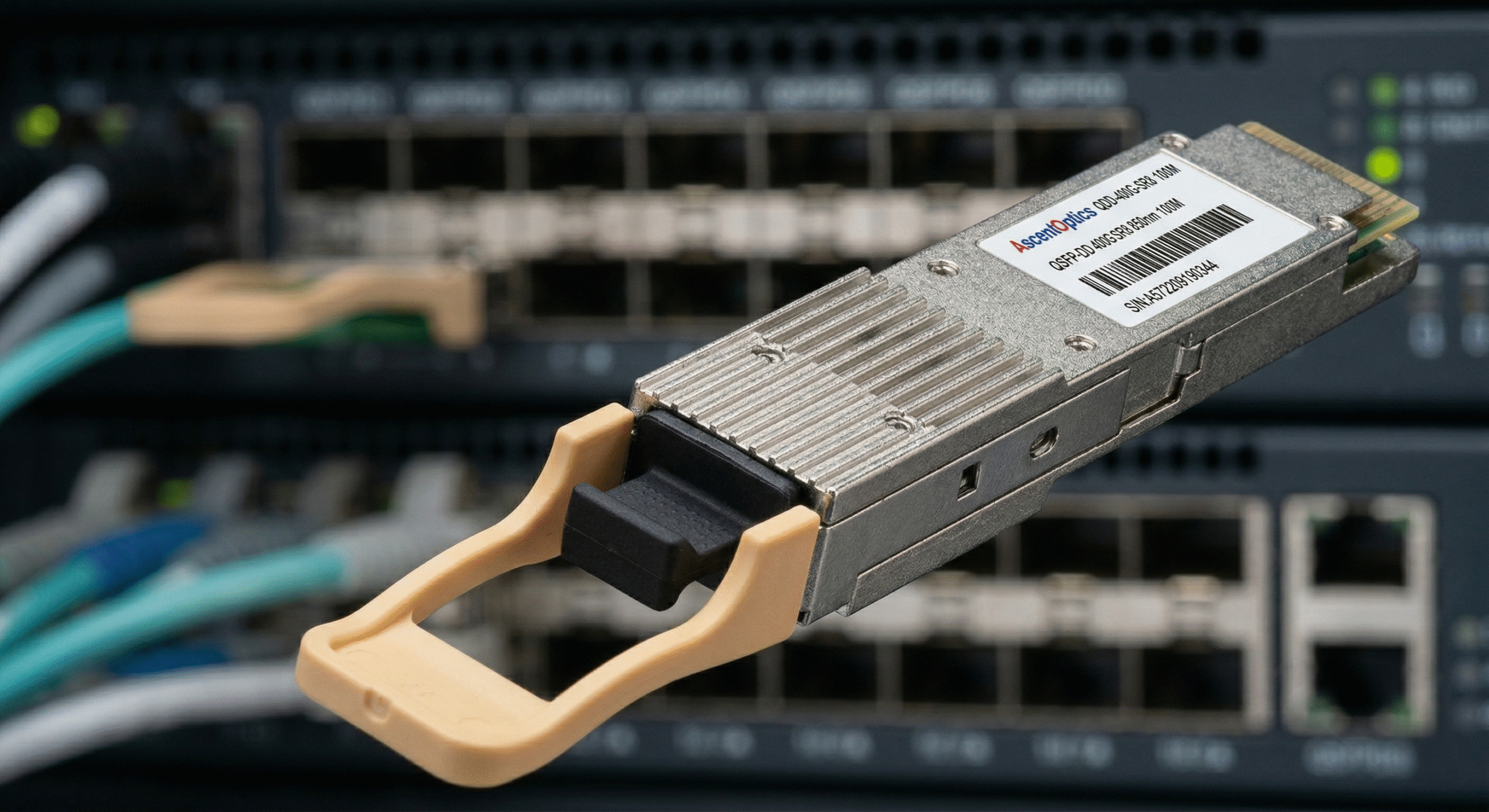
The 400G implementation at the hyperscale data center located in Northern Virginia showed higher power consumption than expected when the facility tested their new system in March 2024. The QSFP-DD optical modules proved responsible for the power consumption problem, which did not originate from the switch ASICs or cooling systems. The 400G ports consumed between 12 and 14 watts—three times the power consumption of their previous 100G system that used 4 watts per port. The company experienced 16 kilowatts of unexpected power consumption because they misjudged their AI training cluster’s 2,000 deployed ports, resulting in additional $140,000 in annual energy expenses.
Data centers must understand QSFP-DD power consumption and 400G transceiver power requirements to effectively plan their operational infrastructure. The shift from 100G to 400G networking delivers higher bandwidth but introduces significant operational challenges due to increased power demands. This guide provides the technical details needed to calculate power budgets, select the right power classes, and manage thermal loads for 400G QSFP-DD deployments.
QSFP-DD Power Consumption by Module Type
The power consumption of 400g qsfp-dd systems depends on which module type and reach requirements and underlying technology. Understanding these differences is essential for accurate infrastructure planning, power budgeting, and thermal design.
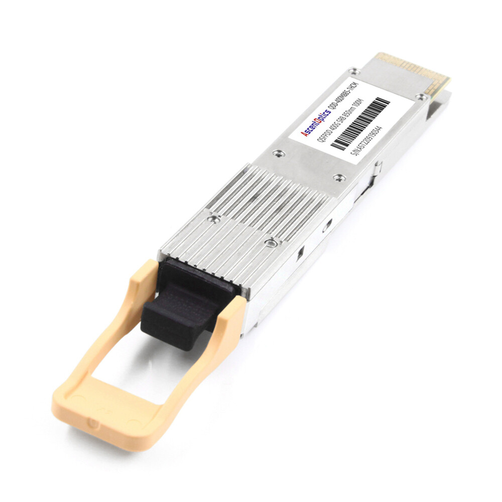
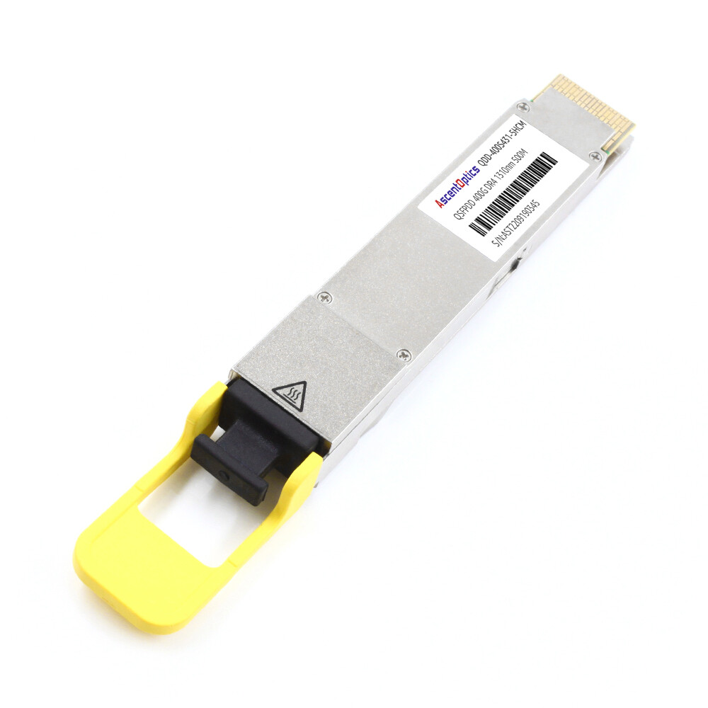
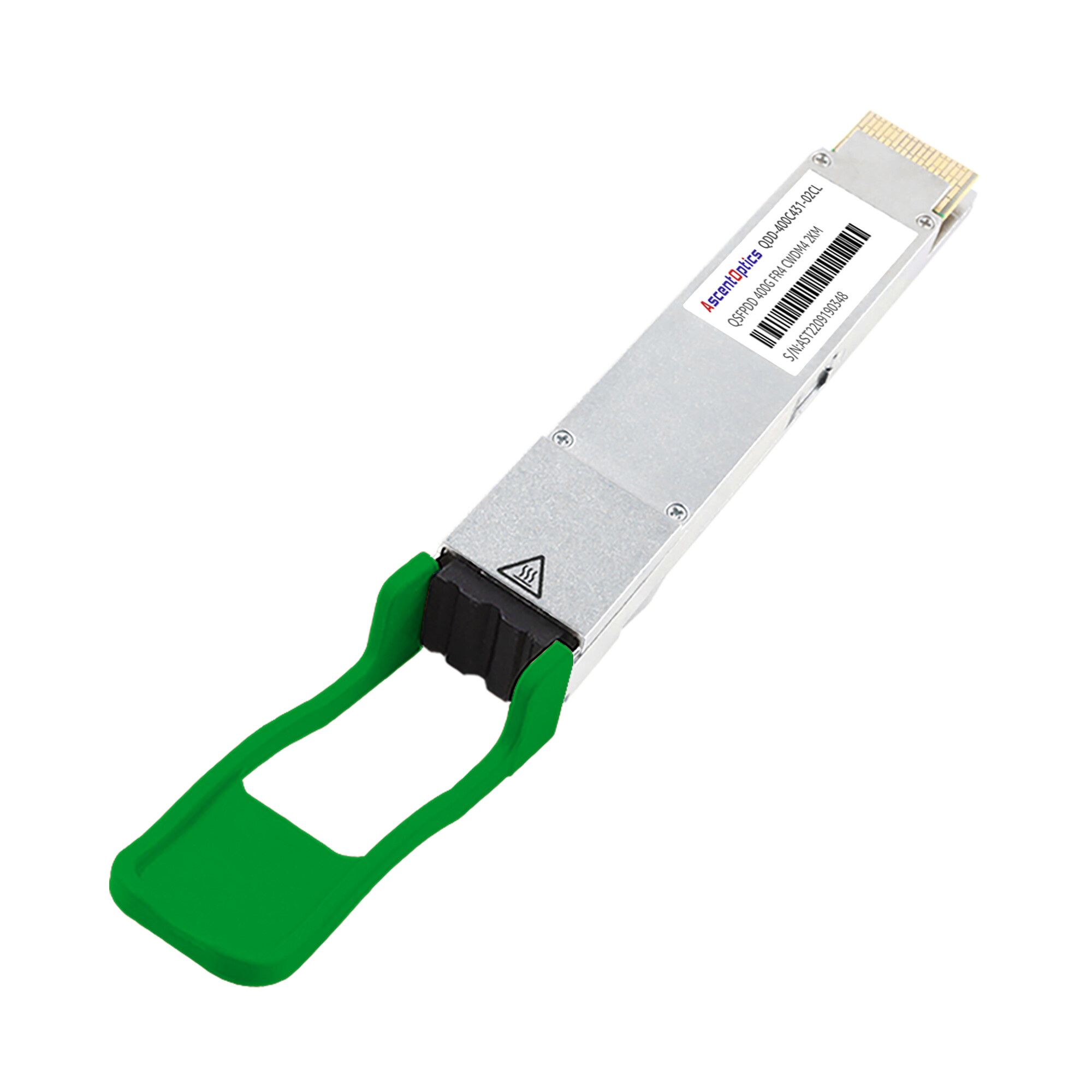
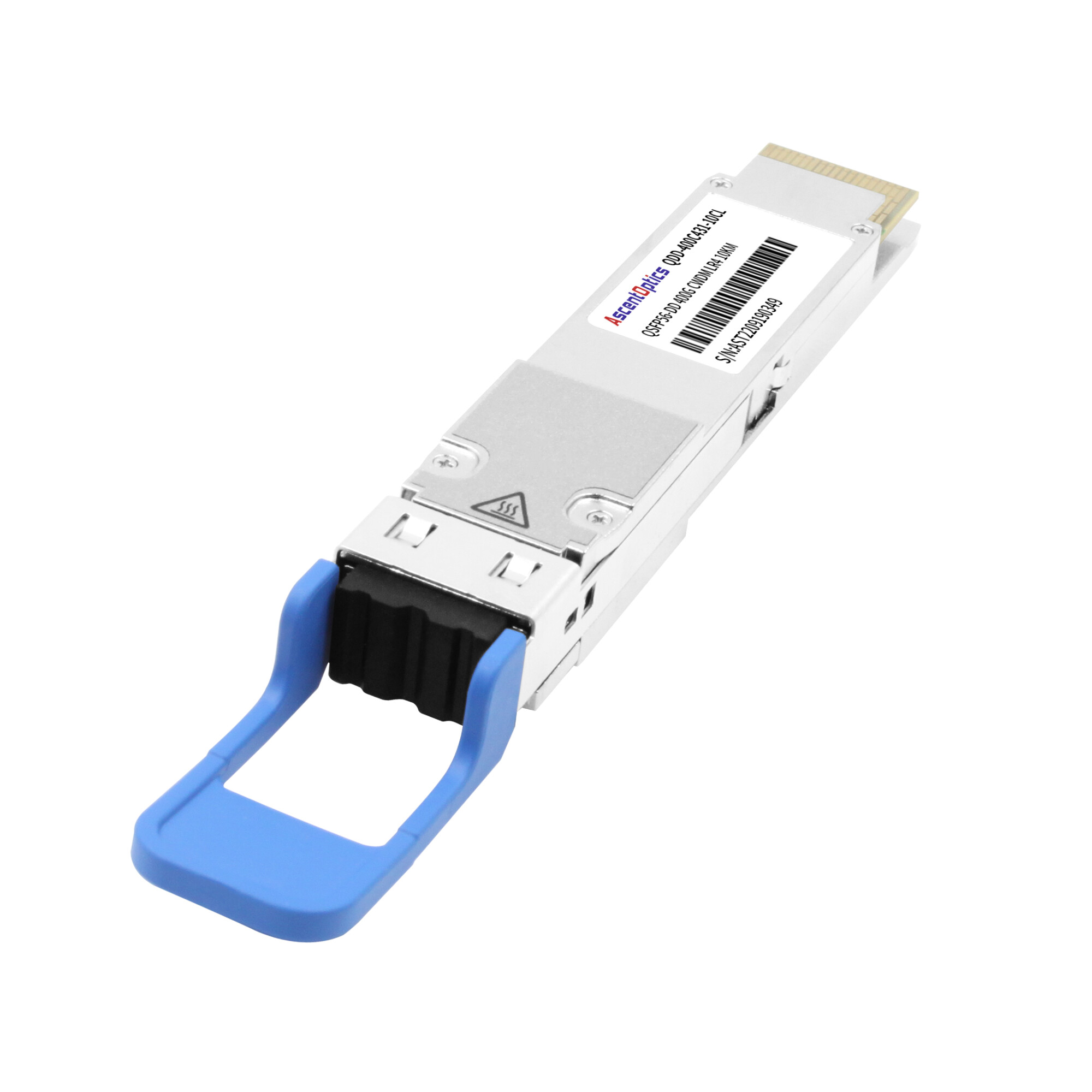
Standard 400G Modules: SR8, DR4, FR4, LR4
Standard 400G QSFP-DD modules consume between 10 and 14 watts under typical operating conditions. The power variation reflects differences in laser count, DSP complexity, and optical amplification requirements.
| Module Type |
Typical Power |
Maximum Power |
Primary Use Case |
| 400G SR8 |
10-12W |
<12W |
Short-reach multimode (100m) |
| 400G DR4 |
9-12W |
<12W |
Data center interconnect (500m) |
| 400G FR4 (Gen1) |
10W |
<12W |
Medium reach (2km) |
| 400G FR4 (Gen2) |
7-10W |
<12W |
Silicon photonics variant |
| 400G LR4 |
12-14W |
<14W |
Long reach (10km) |
| 400G ER4 |
12-15W |
<15W |
Extended reach (40km) |
The latest generation of silicon photonics-based FR4 modules have an as low as 7 watt power usage and within the range to achieve 400G QSFP-DD power consumption by enhancing the design of lasers and simplifying the optical assemblies. Whereas this is a 30% less than the very first-generation’s discrete-laser designs, thus giving reduced temperatures of operations and cooling requirements for the management of qsfp-dd power consumption.
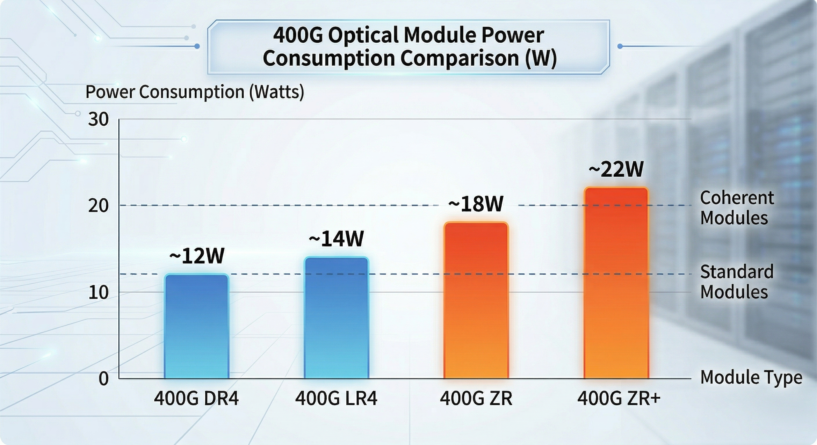
High-Power Coherent Variants: ZR and ZR+
Coherent optical modules for metro and long-haul applications consume significantly more power due to sophisticated digital signal processors (DSPs) and high-performance tunable lasers.
| Module Type |
Typical Power |
Maximum Power |
Application |
| 400G ZR |
15-17W |
<18W |
Metro DCI (80-120km) |
| 400G ZR+ |
17-23W |
<25W |
Extended metro (480km+) |
| OpenZR+ |
16-23W |
<25W |
Multi-rate coherent (100G-400G) |
These high-power variants present unique thermal challenges. A fully populated 32-port switch with ZR+ modules can generate over 700 watts of optical power dissipation alone, requiring careful attention to switch thermal design and data center cooling capacity.
For detailed guidance on selecting and deploying coherent optical modules, refer to our complete guide to QSFP-DD ZR coherent optics.
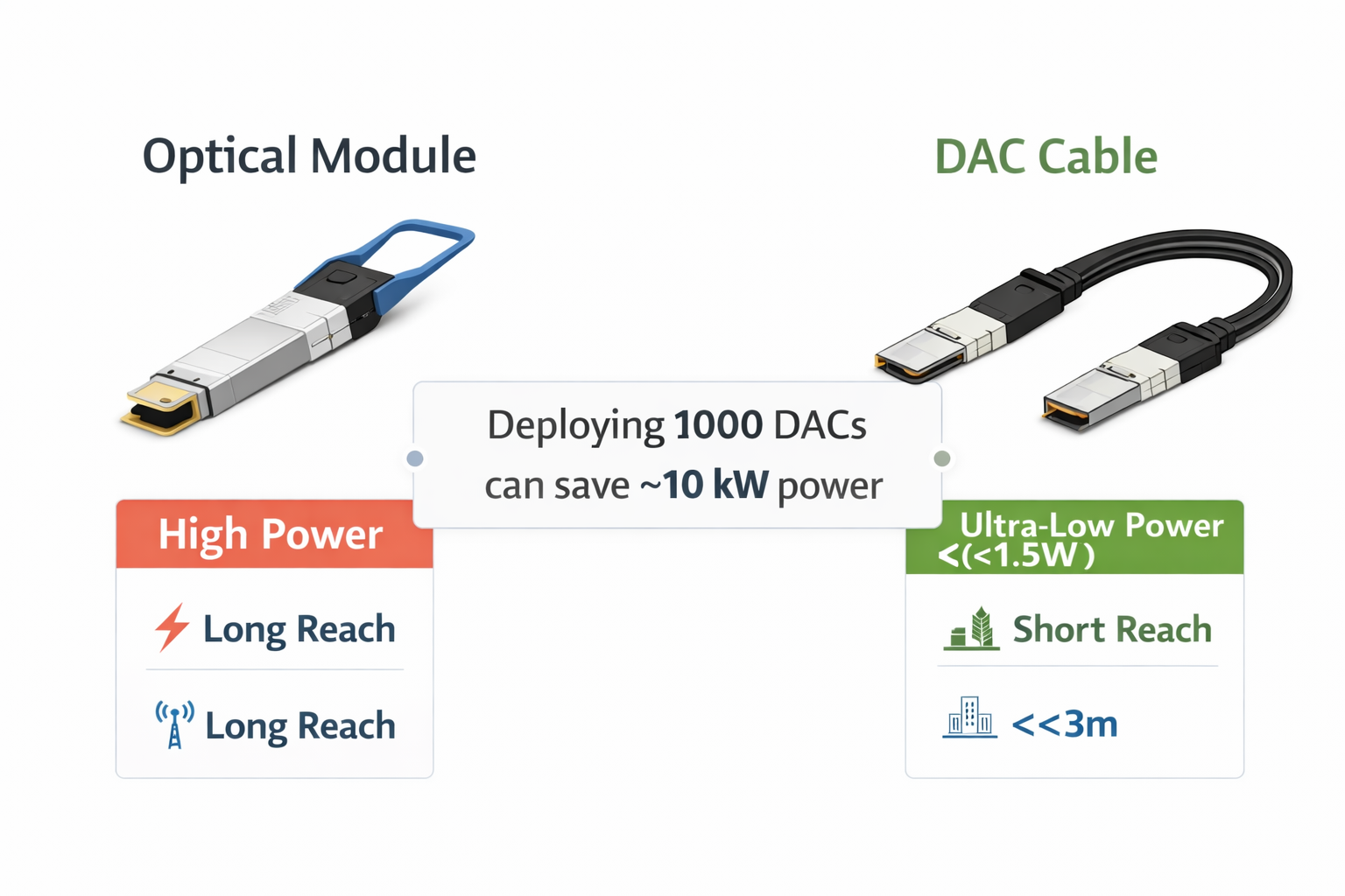
Low-Power Cable Alternatives
For short-reach interconnects within racks or adjacent cabinets, cable alternatives offer substantial power savings compared to optical modules.
Direct Attach Copper (DAC)
- •Power consumption: <1.5W (typically 0.5-1W)
- •Reach: Up to 3 meters
- •Use case: Top-of-rack to server connections
Active Optical Cables (AOC)
- •Power consumption: ~9.5W per end
- •Reach: Up to 100 meters
- •Use case: Intra-row connectivity
Active Electrical Cables (AEC)
- •Power consumption: ~4.5W per end
- •Reach: Up to 2.5-7 meters
- •Use case: Mid-range rack-to-rack connections
The power savings from cable alternatives can be substantial. A data center deploying DAC instead of optical modules for 1,000 intra-rack connections saves approximately 10-12 kilowatts of continuous power draw.
QSFP-DD Power Classes Explained
Power classes are defined in the QSFP-DD MSA to standardize power requirements and ensure compatibility between transceivers and host systems. Understanding these classes is critical for switch selection and power budgeting.
Power Class 6 (Up to 10W)
Power Class 6 modules operate at 10 watts or less, representing the lower power tier of 400G optics.
Typical Applications:
- •400G SR8 multimode transceivers
- •Short-reach single-mode variants
- •Lower-power silicon photonics modules
Switch Compatibility: Most 400G-capable switches support Class 6 without issues. However, older line cards designed for QSFP28 (100G) may not recognize or power these modules.
Power Class 7 (Up to 12-14W)
Power Class 7 encompasses the majority of standard 400G QSFP-DD modules currently deployed in data centers.
Typical Applications:
- •400G DR4 (500m reach)
- •400G FR4 (2km reach)
- •400G LR4 (10km reach)
Switch Compatibility Considerations:
Not all 400G switches fully support Class 7 load breakers. Some very early-generation 400G line cards were designed on the assumption of Class 6 and they may encounter thermal throttling or complete port shutdowns while the Class 7 modules come alive at full (with) traffic load.
Power Class 8 (Above 14W)
Power Class 8 extends QSFP-DD power delivery beyond the original 12W specification to accommodate high-power coherent optics and early 800G modules.
Typical Applications:
- •400G ZR coherent modules
- •400G ZR+ extended-reach coherent
- •800G QSFP-DD client optics (17-18W)
- •800G QSFP-DD line optics (20-25W)
Caution: Not all 400G switches can reliably support Class 8 power levels. Always verify QSFP-DD power consumption specifications per port with the switch vendor before installing ZR/ZR+ or 800G modules.
When planning your 400G deployment, consult our guide to QSFP-DD compatible switches to verify power class support for your specific hardware platform.
Data Center Power Budget Calculator
Accurate power scaling prevents costly infrastructure surprises. The formulas below provide practical approaches to calculating power needs between various scales of QSFP-DD deployment.
Per-Switch Power Calculation
Formula:
Total Switch Power = (Port Count × Module Power × 2) + ASIC Power + Margin
Where:
- •Port Count: Number of 400G ports per switch
- •Module Power: Worst-case power consumption per module (use maximum rated power, not typical)
- •× 2: Accounts for both ends of each link (unless using breakout cables)
- •ASIC Power: Switch chipset power consumption (typically 300-500W for 400G switches)
- •Margin: 20% safety margin for peak loads and future expansion
Worked Example: 32-Port 400G Switch
Optics Power = 32 ports × 14W × 2 = 896W
ASIC Power = 400W (typical for high-density 400G switch)
Subtotal = 1,296W
With 20% Margin = 1,555W
A fully populated 32-port 400G switch requires approximately 1,500-1,600 watts of power budget allocation.
Rack-Level Power Planning
Formula:
Rack Power = (Switch Count × Switch Power) + Cooling Overhead + PDU Loss
Example: 42U Rack with 8× 32-Port Switches
Switch Power = 8 × 1,555W = 12,440W
Cooling Overhead = 12,440W × 0.15 = 1,866W
PDU Loss (2%) = 12,440W × 0.02 = 249W
Total Rack Power = 14,555W (~14.6 kW)
This calculation demonstrates that a single 42U rack filled with 400G switches can approach 15 kilowatts of power consumption, requiring careful attention to rack PDU ratings and data center power distribution.
Real-World Deployment Scenario
Scenario: AI Training Cluster with 400G Interconnect
A mid-sized AI training facility plans to deploy 256 GPUs across 32 servers, with each server connecting via dual 400G ports to a leaf-spine fabric.
Infrastructure Requirements:
- •64× 400G server ports (2 per server × 32 servers)
- •64× 400G leaf switch ports
- •32× 400G spine switch ports for inter-leaf connectivity
- •Total: 160× 400G ports
Power Calculation:
Server-Side Optics: 64 ports × 12W = 768W
Leaf Switch Optics: 64 ports × 14W × 2 = 1,792W
Spine Switch Optics: 32 ports × 14W × 2 = 896W
Switch ASICs: 6 switches × 400W = 2,400W
Subtotal: 5,856W
With 25% Margin: 7,320W
The networking infrastructure for this AI cluster can alone consume over 7 kW of power allowance. Combined with GPU server power (typically 3-5 kW per server), total rack power can exceed 30 kW per rack and demand liquid cooling.
Understanding these power requirements early in the design phase prevents costly mid-deployment infrastructure upgrades. For organizations planning 400G deployments, our comprehensive guide to 400G/800G QSFP-DD optical modules provides additional selection criteria beyond power consumption.
QSFP-DD Power Consumption: Thermal Design and Management
Effective temperature management is important to the potentials that are unlocked through remarkable power uptake. This visibility, destined along thermal principles, holds the promise of ensuring that the lighter modules remain in good working order despite the possibility of breakdown or malfunction.
Thermal Specifications and Limits
Case Temperature Operating Range:
- •Normal operation: 0°C to 70°C
- •Extended temperature variants: -5°C to 75°C
- •Industrial grade: -40°C to 85°C
Critical Component Temperature Limits:
| Component |
Maximum Temperature |
Exceeding Risk |
| DSP Junction |
95-105°C |
Permanent silicon damage |
| nITLA (tunable laser) |
75-85°C |
Wavelength drift, instability |
| TOSA (transmit optics) |
75-85°C |
Reduced output power |
| ROSA (receive optics) |
75-85°C |
Increased error rates |
Exceeding these temperature limits causes degraded performance, increased bit error rates, and potential permanent damage to optical components.
Thermal Throttling and Protection Mechanisms
Modern QSFP-DD modules implement sophisticated thermal protection through the CMIS (Common Management Interface Specification) protocol.
Temperature Thresholds:
| Threshold |
Typical Value |
System Response |
| High Warning |
70-75°C |
Alert logged, monitoring triggered |
| High Alarm |
80-85°C |
Rate limiting may activate |
| Critical/Shutdown |
>85°C |
Module disables optical output |
Thermal Throttling Behavior:
When case temperature approaches warning thresholds, modules may automatically:
- •Reduce transmit optical power through laser bias adjustment
- •Activate or increase forward error correction (FEC) to maintain link integrity at lower signal quality
- •Signal the host system via CMIS interrupts for proactive intervention
These protective mechanisms prevent catastrophic failures but result in reduced link margin and potentially higher error rates.
Airflow Requirements
QSFP-DD modules rely entirely on system-level airflow for cooling, unlike OSFP which incorporates integrated heat sinks.
Minimum Airflow Specifications:
- •Standard modules (≤12W): 150-200 LFM (Linear Feet per Minute)
- •High-power modules (Class 8): 200+ LFM
- •Dense deployments: 250+ LFM recommended
Airflow Direction Considerations:
- •Front-to-back airflow aligns with most data center hot aisle/cold aisle configurations
- •Side-to-side airflow switches require careful rack placement to avoid hot air recirculation
- •Top-of-rack switches may experience reduced airflow efficiency in fully populated configurations
Port Density Thermal Management
High-density deployments create thermal challenges beyond individual module specifications.
Hot Spot Formation:
When high-power (Class 7 or 8) modules are placed in adjacent ports, thermal coupling can create local hotspots. The combined heat output may exceed the cooling capacity of typical switch designs, especially in the middle of line cards where airflow is restricted.
Mitigation Strategies:
- Stagger high-power modules: Distribute ZR/ZR+ or 800G modules across the switch rather than clustering them
- Implement thermal monitoring: Use CMIS telemetry to track module temperatures in real-time
- Design for worst-case scenarios: Assume all ports populated with maximum-power modules
- Consider switch-specific thermal zones: Some switches have variable cooling capacity across the chassis
Engineering Insight: A major cloud provider discovered that clustering 16× 400G ZR+ modules in adjacent ports on a high-density switch caused the center modules to reach 78°C case temperature, triggering thermal alarms. Redistributing the modules to every other port reduced maximum temperatures to 68°C, well within safe operating limits.
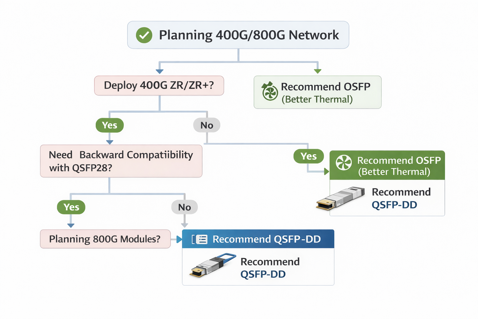
QSFP-DD vs OSFP Power Comparison
The qsfp-dd vs osfp power comparison is a critical decision point for network architects. Form factor selection significantly impacts power capacity and thermal capabilities. Understanding the QSFP-DD vs OSFP power comparison helps architects choose the appropriate platform for their specific requirements.
Power Capacity Differences
| Specification |
QSFP-DD |
OSFP |
| Standard Power Budget |
12-15W |
15-20W |
| Extended Power Support |
Up to 20W (challenging) |
Up to 25W+ |
| Typical 400G Module Range |
10-14W |
12-15W |
| 400G ZR+ Support |
Marginal (15W limit) |
Excellent (20W+ capacity) |
| 800G Module Support |
Limited |
Native support |
OSFP provides approximately 25-33% more power headroom than QSFP-DD, making it the preferred choice for high-power coherent optics and next-generation 800G deployments.
Thermal Efficiency Comparison
OSFP Advantages:
- •Integrated heat sink: Built-in thermal management with open-finned, closed-finned, or flat-top options
- •Superior thermal geometry: Larger surface area and optimized metal casing enable >30% better heat dissipation
- •Cooler operation: Maintains case temperatures below 65°C even at 14-15W power consumption
QSFP-DD Characteristics:
- •System-dependent cooling: Relies entirely on switch-level airflow and thermal design
- •Higher thermal density: Smaller form factor concentrates heat in less volume
- •Thermal challenges at Class 8: High-power modules push the thermal limits of the form factor
Form Factor Decision Matrix
| Deployment Scenario |
Recommended Form Factor |
Rationale |
| Standard 400G (SR8/DR4/FR4) |
QSFP-DD |
Adequate power/thermal, higher density |
| 400G LR4/ER4 (12-14W) |
Either |
Depends on switch platform |
| 400G ZR/ZR+ (15-24W) |
OSFP |
Thermal headroom critical |
| 800G deployment |
OSFP |
Native support, better thermal design |
| Mixed 100G/400G environment |
QSFP-DD |
Backward compatibility with QSFP28 |
| AI/HPC clusters |
OSFP |
Better thermal stability under sustained loads |
QSFP-DD Power Consumption: Optimization Strategies
Several strategies can reduce qsfp-dd power consumption and associated thermal loads without compromising network performance.
Module Selection for Power Efficiency
QSFP112 as Alternative:
QSFP112 (4×100G PAM4) modules consume approximately 30% less power than equivalent QSFP-DD modules, typically 6.5-9.5W compared to 10-12W.
Trade-offs:
- •QSFP112 requires 400G-capable switch ports (not backward compatible with 100G)
- •Slightly different signal integrity characteristics
- •Limited availability compared to QSFP-DD
Silicon Photonics Adoption:
Second-generation silicon photonics-based modules achieve 7-10W for FR4 applications compared to 10-12W for discrete laser designs. The 2-3 watt savings per module translates to meaningful power reductions at scale.
Cable vs. Optical Module Break-Even Analysis
For short-reach connections, cables offer substantial power savings over optical modules.
| Connection Type |
Power per Link |
Typical Reach |
Best Use Case |
| DAC (Passive) |
<1.5W |
<3m |
Within-rack server connections |
| AEC (Active Electrical) |
~9W |
<7m |
Adjacent rack connections |
| AOC (Active Optical) |
~19W |
<100m |
Intra-row connectivity |
| 400G SR8 |
~24W |
<100m |
Short-reach fiber requirements |
Break-Even Distance:
- •DAC becomes impractical beyond 3 meters due to signal integrity limitations
- •AEC provides optimal power efficiency for 3-7 meter connections
- •AOC and optical modules are necessary for connections exceeding 7 meters
Thermal Management Best Practices
Heat Sink Selection:
For high-power deployments, aftermarket heat sinks can improve thermal performance:
- •Finned heat sinks: Increase surface area for air-cooled environments
- •Thermal interface materials: Improve heat transfer between module and heat sink
- •Module-level temperature monitoring: Use CMIS telemetry to identify thermal issues before they cause failures
Airflow Optimization:
- •Maintain minimum 200 LFM across all ports
- •Avoid obstructing switch intake or exhaust vents
- •Consider hot aisle/cold aisle containment to improve cooling efficiency
- •Monitor temperature trends over time to identify degradation in cooling performance
800G QSFP-DD Power Consumption and Efficiency Outlook
The advent of networking at 800G has led to a change in the behavior of power consumption from the other side of the world, both in terms of overall power drawn and efficiency per gigabit.
800G QSFP-DD Power Specifications
| Module Type |
Power Consumption |
Efficiency (mW/Gbps) |
| 800G Client Optics |
17-18W |
21-22 mW/Gbps |
| 800G Line Optics |
20-25W |
25-31 mW/Gbps |
| 800G Coherent |
22-28W |
28-35 mW/Gbps |
Power Efficiency Trends
The industry continues pushing toward lower power per gigabit:
- •400G Generation: 25-30 mW/Gbps typical
- •800G Generation: 15-25 mW/Gbps (improved silicon efficiency)
- •Industry Target: 35 mW/Gbps or lower
As absolute switch chip power increases with 800G, the gain in power efficiency per gigabit becomes even more significant. A fully loaded 800G switch delivers twice the bandwidth of a 400G switch but only at 40-50% more total power.
For organizations planning future network upgrades, our 800G QSFP-DD module guide provides detailed specifications and migration planning guidance.
Conclusion
An urgent requirement during the operation deployment of 400G network designs regarding the power consumption of QSFP-DD modules; It has been established that critical questions regarding power budgeting must be addressed, far in advance planning of the deployment period.
Key principles for managing QSFP-DD power and thermal requirements:
- •Plan for worst-case power: Use maximum rated power specifications, not typical values, for infrastructure sizing
- •Understand power class limitations: Verify switch support for Class 7 and Class 8 modules before deployment
- •Implement thermal monitoring: Use CMIS telemetry to track module temperatures and identify potential issues proactively
- •Consider cable alternatives: Deploy DAC and AEC for short-reach connections to reduce power consumption significantly
- •Choose form factors appropriately: Evaluate QSFP-DD vs OSFP based on power and thermal requirements for your specific applications
- •Design for 800G transition: Factor in higher power requirements for future network upgrades
If you are fielding regular 400G optics or high-power coherent modules, power budgeting and thermal management are essential for network reliability. Lighting up the network without them by underestimating qsfp-dd and 400g transceiver power requirements can end up with expensive pitfalls.
Shenzhen Ascent Optics manufactures a comprehensive range of QSFP-DD transceivers optimized for power efficiency and thermal performance. Contact our engineering team for assistance with power budget calculations and module selection for your 400G deployment.
Frequently Asked Questions
1. What power capability does a 400G QSFP-DD module have?
The 400G QSFP-DD modules could typically pull between 10 and 14 watts, depending on the particular kind. The short-reach SR8 modules usually draw 10-12W, while long-reach LR4 modules need somewhere between 12-14W. In the case of high-power coherent optics like ZR/ZR+, these draw between 15W and as much as 24W.
2. What about Power Class 8 on the QSFP-DD?
Power Class 8 now extends the QSFP-DD power beyond the original specification of 12W in order to manage high-power coherent optics and 800G modules. Class 8 modules can draw over 15 W, presenting a challenge for switches with discrete high-power capabilities.
3. How is the power budget for 400G switches calculated?
Calculate the total power using the equation: (Port count × Module Power × 2) + ASIC Power + Margin. Based on a 32-port case with modules requiring 14W, we are in for around the range of 1,500-1,600 watts included margins.
4. At what temperature does a QSFP-DD module throttle?
Typically, many QSFP-DD modules, when the temperature rises to 70-75°C, trigger thermal protection (warning threshold) and in an extreme case even shut down anyway at an elevated temperature of 80-85°C. The best temperature region for efficient operation without any disturbance in its functioning must be maintained below 70°C.
5. Which one is better for high thermal power: QSFP-DD or OSFP?
For high-power situations, OSFP is generally the first choice due to the additional accommodation of heat sink design and support potential for 15-25W modules. It so happens that QSFP-DD undertakes regular operation of the 400G optics at a leverage of < /= 14W but has real difficulties in thermal terms when in applications across ZR coherent modules.
Post Views: 33