Fiber optics has changed how information moves from one location in a network to another by providing faster and more reliable connectivity essential for various services. Modern-day telecommunications systems heavily rely on fiber optic patch cables, with one constituent, the LC UPC fiber optic patch cable, being more memorable because of ergonomics and performance. This article will mainly focus on explaining and providing information about these cables by looking into their structure, usefulness, and some of the important features that are necessary in today’s networking environments. The author will explore the finer points of an LC UPC fiber optic patch cable and compare it to other similar options available in the market, as well as the efficiency of the optimization of data transmission processes.
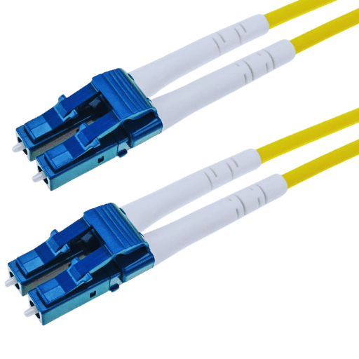
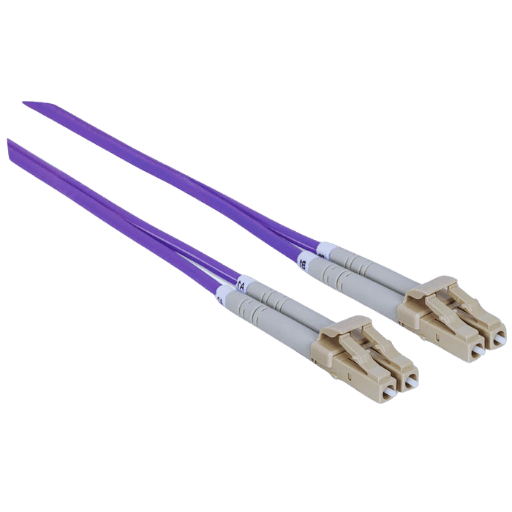
LC UPC fiber optic jumper cables are specialized cables particularly fashioned for inter-telecommunication equipment interconnections in fiber optic systems. LC” is also a type of connector used in fiber-optic devices and, in most cases, is a small, easy-to-use, lucent connector. “UPC” is the abbreviation of Ultra Physical Contact, which is a Polish type on the fiber end face with the goal of decreasing optical return loss. The Lower Fabrications are created since they are the range of Cable, and such Fabricated Orientations are more Lightweight per unit of area and Permit very High Data Transfer Rates with extremely low amounts of any signal that is Lost.
The use of LC connectors in fiber optic cabling is very critical as they are compact and permit high-density interconnections. The design makes use of a 1.25mm ferrule that helps in the exact mating of optical fibers and is specifically made for low insertion loss and pin-point communication. The handling and installation of such devices minimize the maintenance time and increase the general efficiency of the network. They further provide an LC connector which has flexibility as it can be used with either a singlemode or multimode fiber.
Among the polished end face types, the Ultra Physical Contact (UPC) describes the well-known surface roughness finishing of the fiber optic connector. Unlike the standard version, the polish cut in UPC has a smoother surface because of better polishing properties. With this polishing method, optical return losses are lowered as a result of deeper physical contact between the two mated fiber connectors, thereby lessening the amount of light reflected back to the core. UPC connectors are most commonly used in places where low return loss is particularly important, for example, in numerous telecom networks, and in high-rate data transmission systems.
If you look closely, you will quickly identify that the most common type of fiber patch cables is LC UPC. LC UPC patch cables have a variety of uses in many applications in the telecommunication and data communications field. One common use of these cables is within data centers to help provide high-density interconnections in rows of equipment, also known as racks, or amongst different pieces of equipment. Their low insertion and return loss ensures that when these connectors are used, there is high fidelity in the transmission of signals. This is important to prevent the effect of cross-talk, especially in today’s data center environments that have high-speed data networks. At the same time, LC UPC patch cables are used in smaller area networks and larger area networks (LAN and WAN), where they provide connectivity between devices in the network as well as help transmit optical signals over distances of short to medium length. In such networks, they help with the connection of components for telecommunication systems to function well where there are critical components that should work optimally with less signal loss.
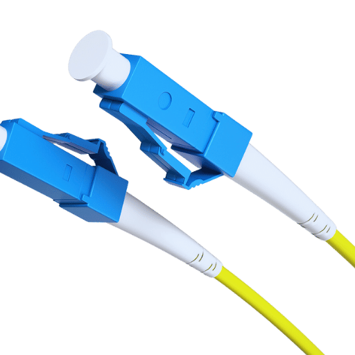
A fiber optic patch cable is contextually made up of several components, namely the fiber core, cladding, buffer coating, strength member, and outer jacket. The fiber core is the light-transmitting material and is usually made of plastic or glass. Another layer bordering the core is a cladding area, which encases the core and bounces the light towards the core through total internal reflection. The cladding remains covered by a buffer coating, which acts as a barrier to mechanical impairments and environmental effects. The strength member helps in carrying blades and tension and is made of aramid yarns. The outer jacket is the last protective layer that covers all the above elements from moisture / mechanical wear, as well as other external influences.
UPC (Ultra Physical Contact) finishing occurs to reduce the connector’s insertional loss, which is the signal’s power degraded due to adding a component into the fiber optic circuit. Connectors that feature a UPC polish have a spherical end face, which reduces the volume of the cavity between two apertures and, hence, lowers the reflection of the signal at the interface. The decrease of reflection is critical in enabling proper transmission of the signal since all the reflected signals are likely to introduce errors to the data and increase the congestion of the network.
Insertion loss is calculated grossly in dB, where a lower value means better insert loss performance. For the most part, the insert loss change for standard UPC connectors is typically in the range of 0.1 to 0.3 dB which makes it very appropriate for use in fields of high accuracy with very little transmission loss. In addition, field data indicates that reducing the polishing granularity, i.e., using polishing films of finer grits (generally, 0.3 microns in range), which are obtainable, further plays a role in lessening the connector’s surface roughness, enabling perfect signal transmission.
Wider research demonstrates that with appropriate UPC polishing techniques, the insertion loss variance exhibits a relatively small deviation even across different connectors. Thus, the impacts of the UPC polish on insertion loss are significant as it improves the physical junction of the two connectors and the quality of the signal in high-end fiber optic networks.
When it comes to singlemode and multimode in LC UPC patch cables, the critical aspects that vary include core size, transmission distance, and applications. Singlemode cables have a smaller core size of about 8-10 microns, enabling the fibers to carry light well with less loss and, most times, run above 10 kilometers. Long-distance transmission. Multimode cables with a core size of about 50 or 62.5 microns transmit signal over many light paths, so they can’t extend beyond several kilometers because of the large modal dispersion annexed to the cables. Singlemode fibers find frequent application in telecommunication systems, offering ideally high bit rate transmission over long distances. Multimode fibers on the other hand are more practical in situations that require shorter range high data rate transfers, like in datacenters or local area networks (LAN) as they are less expensive and easier to install. With this consideration, all of these aid a type of statement analysis that focuses on the application meant for and its performance requirements.
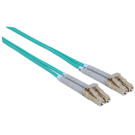
In fiber optic networks, deciding on duplex or simplex systems depends on the work to be performed. Duplex fiber optic cables consist of two side by side fibers, permitting the transmission of data in both directions at the same time. This type of configuration is usually applied on devices that require both transmission and reception of data in a short period, such as switches and servers found in data centers that operates in a high bandwidth environment.
Simplex fiber optic cables consist of one optical fiber which carries a single direction of transmission, and are therefore used in specific cases where data has to be transmitted only in one direction and at one time. Simplex cables are usually used when the communications circuitry is limited without the need for duplex working.
Duplex cables are internally constructed in such a way that two connectors are used on either end, making it possible to connect devices that operate on bi-directional data transmission. As a result, they make it possible to build a network with high the density, and raises the level of reliability of the networks. Instead, simplex cables come with one connector at each end and are, therefore, easier to install and also bring down costs in cases where systems do not need duplex connections.
To summarize, simplex and duplex fiber optic cable depends mainly on the data transmission requirements, system design and budget, the former will take into more complicated systemic issues at the expense of more cost effective components.
The type of jacket used on fiber optic cables is important for safety, compliance, and practical functionality in different situations. LSZH, or Low Smoke Zero Halogen, jackets are fire-resistant materials that are specially made to prevent the emission of harmful smoke and corrosive smoke in case of a fire. As the latter implies, PVC jackets are quite popular, and their ease of use makes them suitable for numerous applications; however, they, however, produce higher smoke and toxic gases during burning. Plenum-rated jackets for use in areas exposed to the passage of air, especially in air conditioning spaces such as ceilings, are manufactured to very rigid standards to mitigate the burning and fuming of the area. Depending on the situation, some materials are better than others, which is a function of the environment, safety, and usability.
While measuring the cable length, parameters such as attenuation of the signal, latency, or the ease of its installation are of primary importance. In most cases, shorter lengths, for example, a metric of 1m, will register a significant decrease in attenuation, resulting in the best signal quality. Nevertheless, for longer distances, some augmenting strategies, such as the use of signal boosters or repeaters, may be laudable to avoid uneven performance. Moreover, such cable lengths after a specified distance are quite difficult to route and require a specific bending radius to avoid breakage. Effective cable management and proper layout are critical to protect the integrity of the system and guarantee the system’s consistency with the principles across any deployment situation.
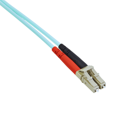
For maximum accuracy when installing the fittings, it is always worth beginning with a careful wipe of all connector surfaces using a clean cloth soaked in permitted alcohol. While holding the LC UPC connectors, solder without turning the pigtail. Do not attach the connector until a clicking sound is heard. The designer shall always adhere to the minimum bend radius in order to prevent the micro-bending of the fibers. Worn, degraded and damaged cables should be checked on a regular basis, as well as other systems, to keep them performing and functioning properly.
Oftentimes, maintenance of LC UPC fiber optic patch cables is ignored which shortens their lifespan and often affects the performance. To prevent this, a proper maintenance schedule should be developed and adhered to.
Through the adherence to the above-mentioned processes, companies will be able to maintain the intactness and the fiber optic resources which are important in ensuring that there is no interruption of network operations.
In working with LC UPC fiber optic patch cables or any other patch cords, it is expected that some problems will arise from time to time and such issues need to be identified and resolved quickly to ensure the desired performance is observed.
If such issues are identified and resolved in time, the network will be steady and functioning.
Due to its larger core diameter allowing multiple light paths, multimode fiber is well suited for short data transmission distances such as campuses and data centers. This characteristic allows for greater modal dispersion, limiting it for longer usage. On the other hand, singlemode fiber, which has a narrow core is appropriate for long-distance and high bandwidth applications where the signal has to be preserved in long distances. Singlemode fiber reduces modal dispersion, which enhances its utilization in telephone and cable television networks, which require a long-range and superior quality.
The choice between OS2 and OM3 fibers is governed by the application and the needs of a given network. OS2 fiber, which is intended for long-distance transmission of data, is a singlemode fiber designed for outdoor purposes and for long-haul use, particularly in telecommunication and carrier networks. This is because it has very low loss and distortion features, and as such, it can efficiently work for long-range interconnection of more than a few kilometers.
However, OM3 fibber is a multimode choice that performs well on shorter distance applications, usually located indoors in facilities such as data centers, local area networks LANs, and the like. It has the capacity of transmitting high bit rates in hundreds of meters with the aid of high bandwidth & mainly used with gigabit and 10 gigabit ethernet. OM3 features a cost-effective installation with only moderate speed extending to a few meters. Simply put, the distance, bandwidth the installation requires, and the economic factors along with environmental circumstances.
A: An LC UPC fiber optic patch cable refers to a fiber patch cord with LC (Lucent Connector) ultra physical contact Polished connectors. Their primary function is interconnecting transceivers, switches, patch panels or any other devices for efficient data transmission.
A: An aqua LC to LC UPC fiber cable is commonly used in data centers and enterprise networks which require OM4 fiber to support high capacity networks that operate over longer distances. The aqua color is commonly used in ordinations with multimode fiber optic systems.
A: An LC to LC UPC patch cord is a fiber optic cable using LC connectors but instead incorporates UPC polishing on the tips to Reflection Loss Squeeze back Reflection Loss of Olympus knives better than that of Active polishing. These cords are applicable where there is a significant requirement for accuracy and minimal disruption in the signal path.
A: Even when the patch cable is under strain, the ceramic ferrules in an LC UPC fiber patch cable allow proper positioning of the optical fibers, thus enhancing the level of performance while minimizing signal attenuation. They are also hardwearing and offer great resistance to abrasion thus promoting the durability of the fiber patch cable.
A: The color aqua is also very common in OM3 and OM4 multicore LC to LC UPC cables. The color coding schemes are ensured to facilitate the identification of the type of fiber cable that is essential in the prevention of wrong usage or connection to other devices within the fiber communication network.
A: The mechanical protection to the internal fibers also includes the cable jacket in an LC UPC fiber optic patch cord and protects them from any physical damage thereby ensuring the cable is durable. Depending on the installation environment requirements there are different cable jackets for example riser rated or plenum rated jackets.
A: Network performance is enhanced in the use of a singlemode duplex LC UPC fiber cable in that it allows the use of two separate fibers for transmitting and receiving over the same cable, fully enabling full duplex communication. This arrangement facilitates faster data rates and reduced cross-talk transmissions, which is particularly important in high data rate applications such as 10Gb Ethernet.
A: In the event that a fiber optic patch cord is needed for use in a network certain factors must be taken into account. Among these factors are the type of fiber, single mode or multimode, type of connectors, for example LC to LC UPC, core diameter of the fiber, cable length, connector quality for example, optical fiber connectors with ceramic ferrule and the location of use of the cable, indoors, outdoors plenum or riser.
A: Invoices stating that quality power is tested through testing of insertion loss and return loss are issued for LC to LC UPC fiber patch cables. These ensure that the cable can effectively carry the required level of signal. Quality cables will demonstrate minimal insertion loss and high return loss. This means that data transmission using high cable quality will be efficient and effective.