Every PAM4 datasheet repeats the same number: about 9.5 dB of SNR penalty. Almost none explain where it comes from, why an optical budget sometimes uses 4.8 dB instead, or why that one number decides whether a module reaches 2 km or 10 km and how many watts it burns getting there.
Here is the part the shorthand hides. The PAM4 SNR penalty is not extra noise added to your link. It is the distance between decision levels that disappears when one NRZ eye becomes three PAM4 eyes. That missing distance is what forces DSP equalization, FEC, and the power budget that comes with them.
What Is the PAM4 SNR Penalty?
The PAM4 SNR penalty is the noise-margin loss caused by splitting one NRZ eye into three smaller PAM4 eyes. Adjacent levels sit one-third as far apart, costing about 9.54 dB at the same baud rate in the voltage domain, or about 4.8 dB on an equal-bit-rate optical power basis.
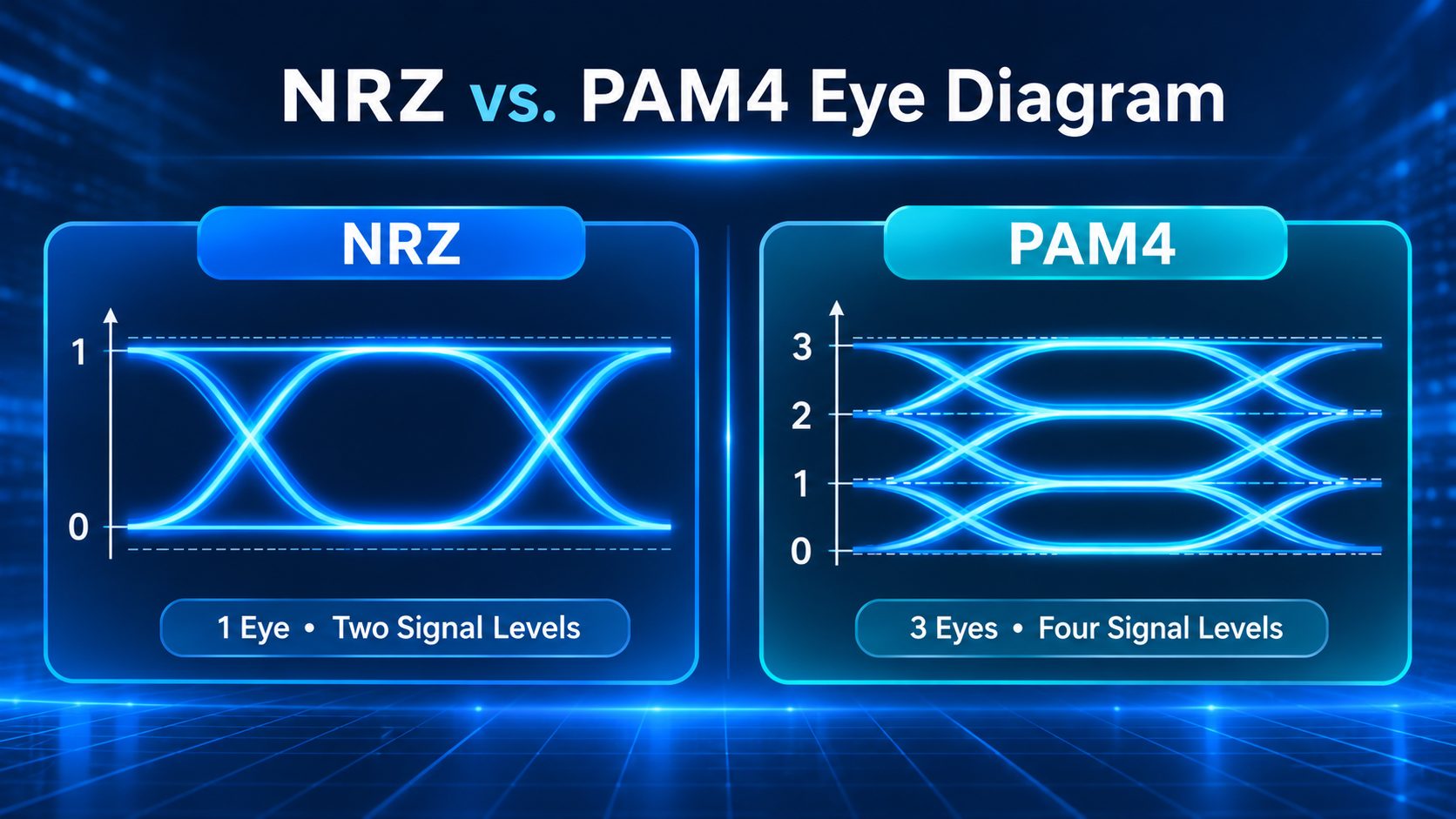
NRZ asks the receiver to choose between two levels. PAM4 asks it to choose among four, with three decision thresholds instead of one. The total swing is the same, but each decision now has less room for noise. That is why a link that ran clean at 25G NRZ can struggle at 50G PAM4 even when the fiber, connectors, and optics are nominally fine.
Why Four Levels Cost 9.5 dB (and When It Is Only 4.8 dB)
For the symbol-level version of this story, see our PAM4 modulation fundamentals. The budget-level version follows.
The Geometry: One Eye Becomes Three
Draw an NRZ eye and you get one opening from the low level to the high level. Draw a PAM4 eye, and you get three openings stacked between four levels. The levels sit at 0, one-third, two-thirds, and full amplitude. Adjacent levels are one-third as far apart as the NRZ levels were.
The voltage penalty is 20 log10(1/3), which is 9.54 dB. That is the number behind the industry shorthand. Add transmitter nonlinearity, level compression, and imperfect level separation, and measured penalties land closer to 11 dB.
In practice, the inner eyes are the fragile ones. They have the same noise as the outer eyes but the least room to absorb it.
Electrical vs Optical: Why the Number Changes
Here is where many datasheets become ambiguous. Electrical SNR is a voltage ratio, so a three-fold reduction in level spacing is 20 log10(3), or 9.54 dB. Optical SNR is a power ratio, so the same three-fold reduction is 10 log10(3), or 4.77 dB.
The commonly cited 9.5 dB figure describes the reduction in adjacent-level voltage spacing when PAM4 is compared with NRZ at the same overall signal swing. A 4.8 dB figure may appear in optical power-based comparisons, but it uses a different measurement basis and should not be treated as a direct conversion of the electrical SNR penalty. Actual system penalties depend on receiver noise, BER targets, and implementation conditions.
| Basis |
Domain |
Formula |
Penalty |
Where you see it |
| Equal baud rate |
Voltage |
20 log10(1/3) |
-9.54 dB |
SerDes, oscilloscope, electrical SNR |
| Equal bit rate |
Optical power |
10 log10(3) |
-4.77 dB |
OMA, receiver sensitivity, link budget |
| With nonlinearity |
Voltage |
Empirical |
About -11 dB |
Real transmitter measurements |
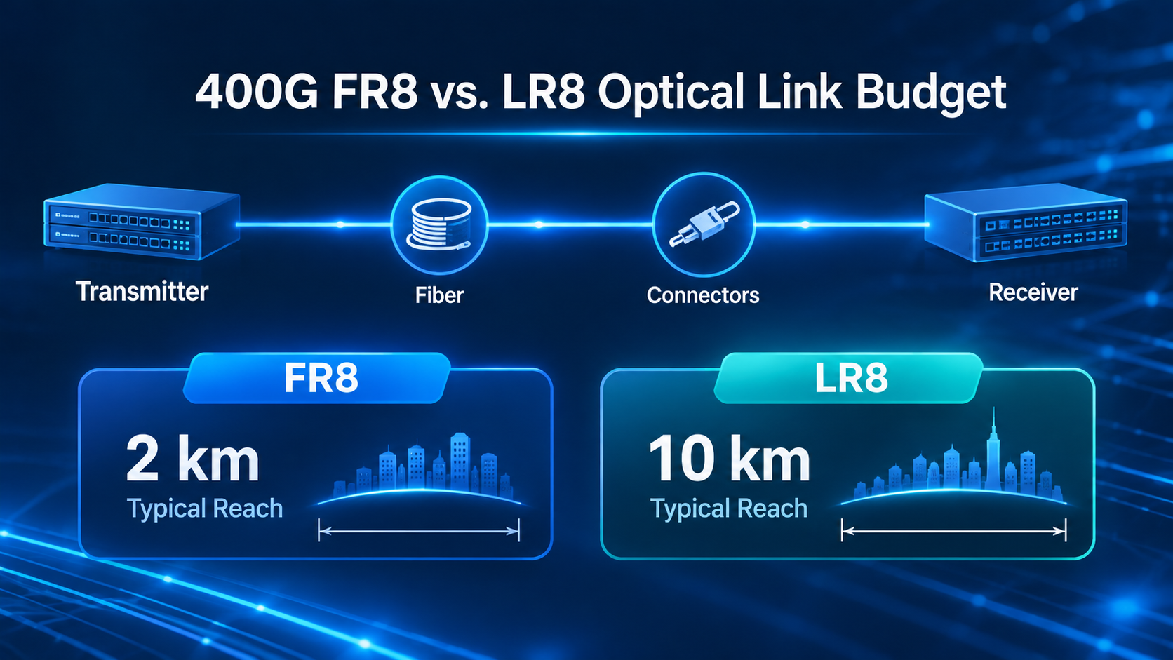
The IEEE 802.3bs 400G budgets use a 5.0 dB modulation penalty for FR8 and LR8, which is close to the optical power basis plus implementation margin.
The Other Side of the Ledger: Half the Baud Rate
At the same gross bit rate, PAM4 carries two bits per symbol, requiring approximately half the symbol rate of NRZ. For example, a 100 Gb/s lane using NRZ requires roughly twice the baud rate of a comparable PAM4 lane, although actual Ethernet line rates depend on encoding and interface specifications.
Channel loss rises steeply with frequency. Halving the frequency often removes more loss than the 9.5 dB penalty adds, which is why PAM4 became the default above 25G to 50G per lane. The trade works because the channel improves faster than the eye shrinks.
That is the comparison in our PAM4 vs NRZ guide, which covers when each format wins. The point here is narrower: the 9.5 dB penalty is the price of admission, not the whole cost of the link.
How PAM4 SNR Shows Up in a Real Link
OMA, TDECQ, and Pre-FEC BER
Three measurements translate the penalty into something you can test. OMA (Optical Modulation Amplitude) is the difference between the average optical power levels representing the logical high and low states. It indicates the transmitter’s optical modulation strength and is an important parameter in evaluating transmitter performance and link budgets.
TDECQ measures the transmitter’s power penalty against an ideal transmitter. It is not a receiver sensitivity number, and it is not link margin. Spec maxima typically sit at 3.1 to 3.4 dB depending on the PMD; good modules measure 1 to 2 dB.
Pre-FEC BER is the error rate before correction. Optical links typically target 2.4E-4 for KP4 FEC, while electrical VSR and MR interfaces target 1E-6 and long-reach electrical interfaces target 1E-4.
The following values are theoretical estimates for an idealized PAM4 receiver under a specific noise model. Actual SNR requirements vary with receiver implementation, channel conditions, and BER targets.
| Pre-FEC BER |
Required slicer SNR |
| 1E-6 |
About 20.4 dB |
| 1E-9 |
About 22.5 dB |
| 1E-12 |
About 23.9 dB |
These are slicer SNR figures, not OSNR. They tell you how much margin the decision circuit needs before FEC closes the rest.
A 400G LR8 Budget, Line by Line
Take a 400G LR8 link: eight 50G PAM4 lanes at 26.5625 GBd, 10 km reach. The standard budget is 13.5 dB. Fiber and connector insertion loss consumes 6.3 dB. Modulation and other penalties consume 5.0 dB. What remains is 2.2 dB of optical margin.
Now compare 400G FR4 at 2 km. The budget is 11.0 dB, insertion loss is 4.0 dB, and the same 5.0 dB penalty leaves 2.0 dB of margin. The fiber is five times shorter, but the margin is nearly twice as large.
| Parameter |
400G FR4 (2 km) |
400G LR8 (10 km) |
| Power budget |
11.0 dB |
13.5 dB |
| Fiber and connector loss |
4.0 dB |
6.3 dB |
| Modulation penalty |
5.0 dB |
5.0 dB |
| Optical margin |
2.0 dB |
2.2 dB |
The reach wall is not the fiber. It is the margin.
Where DSP and FEC Enter
Equalization recovers some of the lost eye. Feed-forward and decision-feedback equalizers reshape the channel response, while the DSP adapts the coefficients per lane. FEC then relaxes the raw BER requirement from roughly 1E-12 to 2.4E-4, which is the difference between an impossible link and a production one.
The details of that chain belong in our PAM4 DSP and FEC guide. For this budget, the takeaway is simple: DSP and FEC buy margin, but they do not create it for free. They consume power and add latency.
The PAM4 Reach Wall
The Reach Ladder
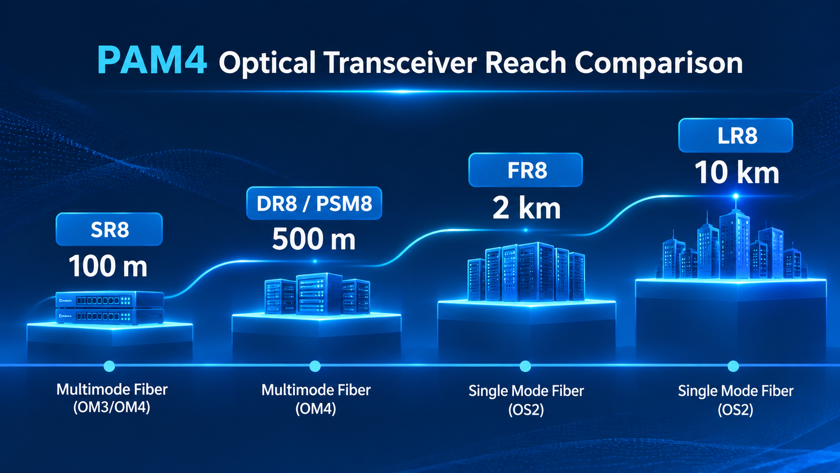
PAM4 reach is a ladder, not a single number. SR8 runs about 100 m over multimode fiber. DR8 and PSM8 reach 500 m over single-mode. FR8 reaches 2 km. LR8 reaches 10 km.
At 100G per lane, the 2 km budget is 7.7 dB, and the 10 km budget is 10.2 dB. Insertion loss rises from 4.0 to 6.3 dB, and penalty allocation rises from 3.7 to 3.9 dB. The extra fiber eats most of the extra budget.
At 200G per lane, the same 10 km becomes harder again. Higher baud rates tighten timing, increase dispersion sensitivity, and shrink the margin left for MPI and connector reflections. SOA-assisted designs and better EMLs extend the reach, but they do not repeal the budget.
Why 10 km Is the Practical Ceiling
For many conventional direct-detect PAM4 applications, 10 km is an important practical reach point. Beyond this distance, link-budget constraints, dispersion, and receiver sensitivity become increasingly challenging. Depending on the required reach and capacity, coherent optics may offer a more suitable solution.
When the Answer Is Coherent
Coherent optics use phase and polarization, not just intensity, so they recover far more sensitivity and spectral efficiency. That is why 40 km, 80 km, and longer links move to coherent rather than stretch PAM4.
The boundary is not sharp. Short-reach coherent and extended-reach PAM4 overlap in the middle. The decision comes down to reach, cost per bit, power, and whether the link needs coherent features such as flexible modulation.
If you are selecting between 2 km and 10 km variants, our 800G optical transceiver guide covers the form-factor and variant trade-offs.
The PAM4 Power Wall
Where the Watts Go
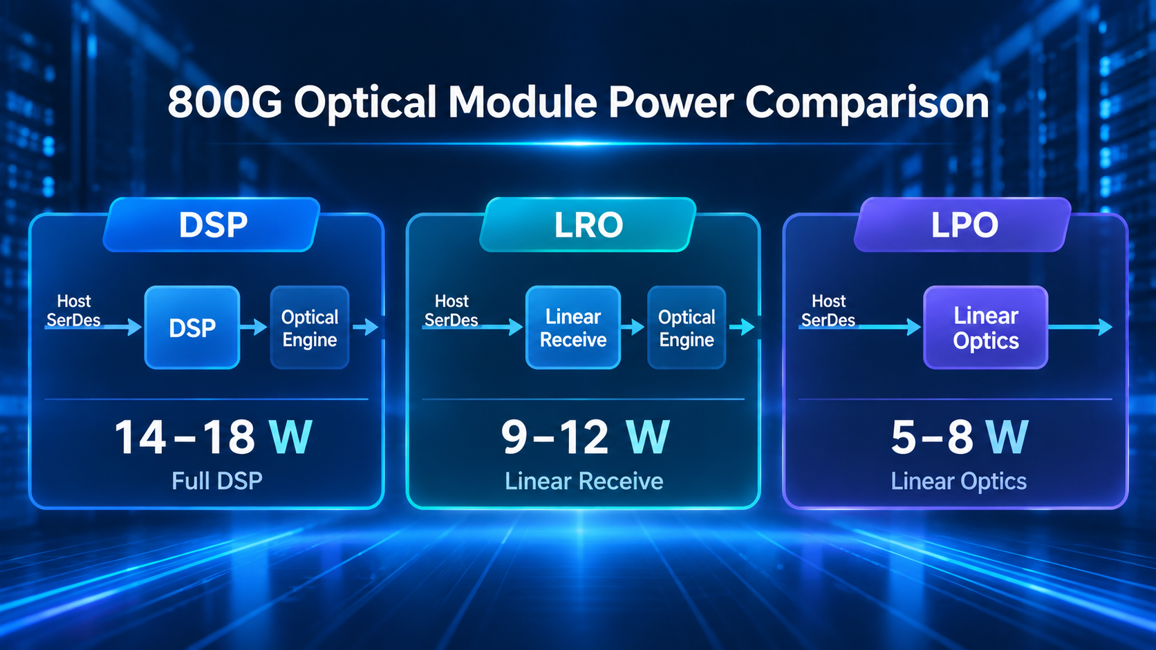
A DSP-based 800G module typically draws 14 to 18 W. At 800G, that is roughly 17.5 to 22.5 pJ/bit. A 1.6T DSP module commonly draws 25 to 35 W. A 51.2T switch filled with 32 of those modules can draw about 1 kW from the optics alone, before the switch ASIC and cooling.
The DSP can account for a substantial portion of the module’s power consumption, although its share varies with the DSP architecture, optical engine, and module design. Lasers, drivers, TIAs, and control electronics take the rest. That split matters because it explains why removing the DSP changes the power profile so much.
| Module type |
Typical power |
Efficiency |
| 800G with DSP |
14 to 18 W |
17.5 to 22.5 pJ/bit |
| 800G LRO |
9 to 12 W |
11 to 12 pJ/bit |
| 800G LPO |
5 to 8 W |
7 to 9 pJ/bit |
| 1.6T with DSP |
25 to 35 W |
15.6 to 21.9 pJ/bit |
| 1.6T LPO |
12 to 15 W |
7.5 to 9.4 pJ/bit |
Our 800G power consumption breakdown covers per-variant wattage and cooling impact.
Why More Lanes Mean More Power
Each lane requires dedicated high-speed signal processing and associated optical or electrical components. Depending on the optical architecture, lasers may be implemented individually or shared across multiple channels. Eight 100G lanes mean eight of those chains. Four 200G lanes mean four chains, but each chain runs at twice the baud rate and needs more equalization and better SNR.
Lane count and per-lane baud rate both push power. That is why 4x200G does not automatically halve the power of 8x100G, and why 1.6T does not simply double 800G wattage.
The Compound Penalty
Higher baud rates reduce margin. Lower margin demands more equalization and stronger FEC. More equalization and FEC demand more DSP work. The power bill rises at both ends of the link.
At some point, the cost is not the module alone. It is the cooling, the rack power, and the number of modules you can fit on a switch faceplate. That is the power wall.
How LPO Reclaims Power Without Repealing the Penalty
What LPO Removes and What It Moves
Linear pluggable optics remove the DSP from the module and let the host switch SerDes perform equalization. An 800G LPO module typically draws 5 to 8 W, or about 7 to 9 pJ/bit, roughly 40 to 50 percent below a DSP-based module.
LRO (Linear Receive Optics) uses a linear electrical interface on the receive path, reducing or eliminating receiver-side DSP processing in the module. Its transmit-side architecture may vary depending on the implementation.
The SNR Cost
The penalty does not disappear. It moves. The host SerDes must now match the module’s analog response, compensate for the channel, and hold the PAM4 eyes open without the module DSP’s adaptive equalization.
That makes host-to-module interoperability the critical risk. A module that tests clean on a bench can fail in a switch if the SerDes tuning profile does not match. Practical LPO reach today is about 500 m, not 10 km.
The LPO-MSA 400G-FR4-LPO specification, for example, covers 0.5 to 500 m at 53.125 GBd PAM4. That is a real deployment envelope, and it is deliberately short.
When LPO Is the Right Trade
LPO fits short-reach scale-up fabrics, controlled host and module pairings, and halls where every watt matters. LPO may provide less module-side digital signal processing and diagnostic visibility than DSP-based optics. System-level monitoring capabilities therefore depend on the module design and host platform.
For the product-level mechanics and qualification checklist, see our 800G LPO guide. The SNR point is the one to carry into procurement: LPO lowers power by moving equalization, not by making PAM4 more tolerant of noise.
Frequently Asked Questions
What is the SNR penalty of PAM4?
About 9.54 dB at the same baud rate in the voltage domain, or about 4.8 dB on an equal-bit-rate optical power basis. Real transmitters with nonlinearity often land near 11 dB.
Is PAM4 9.5 dB worse than NRZ?
At the same symbol rate, yes. At the same data rate, PAM4 runs half the baud rate, so channel loss is lower. The net result depends on the channel, not on the penalty alone.
Why do some sources say 4.8 dB instead of 9.5 dB?
They are using different domains. 9.5 dB is a voltage ratio; 4.8 dB is a power ratio. Both describe the same three-fold reduction in level spacing.
What SNR does PAM4 need?
Roughly 20.4 dB at BER 1E-6, 22.5 dB at 1E-9, and 23.9 dB at 1E-12 at the slicer. Those are pre-FEC targets; FEC closes the remaining gap.
Why is PAM4 limited to about 10 km?
Because the link budget runs out, not because fiber stops working. A 400G LR8 link at 10 km leaves about 1.9 dB of optical margin, which is thin for aging, splices, and connectors. Beyond that, coherent is usually the better answer.
Does PAM4 use more power than NRZ?
At high lane rates, yes, mostly because of the DSP and the lane count. Per bit, a newer PAM4 module can be more efficient than an older NRZ module. The comparison has to be at the same data rate and reach.
How much power does an 800G PAM4 module use?
About 14 to 18 W with a DSP, 9 to 12 W with LRO, and 5 to 8 W with LPO. These are indicative ranges; confirm with the vendor at your operating temperature.
How does LPO reduce power if the SNR penalty remains?
It removes the module DSP and moves equalization to the host SerDes. The penalty remains, but the module no longer pays for the DSP. The trade is shorter reach and tighter host-module interoperability.
Post Views: 189