This blog will thoroughly explain the advancements in the techniques utilized for performance and efficiency in optical networks and the newly created devices suitable for telecommunication splits based on fiber optics. On a fundamental level, telecommunications, data centers, and network infrastructures are entirely based on modern technology, enabling commands to be executed within nanoseconds.
Data centers are defined by their ability to bring a cross of deregulated dimensions to various places. Electricity and wireless networks transmit data and build the modern technological world, benefiting humanity. The Fiber Optic Splitter Diary entails just such devices that those interested in contemporary technology and telecommunications should begin learning about immediately.
What is an Optical Splitter?
An optical splitter is a passive device that operates in fiber optic networks to split a single optical signal into multiple outputs or merge several signals into a single output. It principally aids in distributing optical signals across different endpoints, for example, in Passive Optical Networks (PON).
Optical splitters are key in modern telecommunications infrastructure. They ensure light signals are divided evenly or proportionally without external power.
Understanding the Basics of a Fiber Optic Splitter
A fiber optic splitter divides the incoming optical signal into two or more outputs or merges multiple signals into one output. These devices are passive, meaning they do not need any external power source. Factors such as split ratio, insertion loss, and uniformity, which dictate how efficiently the signal is distributed among the outputs, determine performance. To achieve multiple destinations from a single point, PONs use fiber optic splitters for the economical and efficient transmission of optical signals.
How Does an Optical Splitter Work?
An optical splitter works by taking in a signal during the optical communication process and splitting it into different output signals. This process can be done using high-quality optical parts that maintain the wavelength and quality of light while breaking it. The performance of the splitter depends on two factors: the split ratio, which measures how the output signal is distributed among the various outputs, and insertion loss, which is the measure of loss of the signal during the process of splitting. These devices are configured to ensure that they are uniform in distribution, which is ideal for applications in Passive Optical Networks (PON), which require single signals for numerous end users.
Types of Splitters Used in Modern Networks
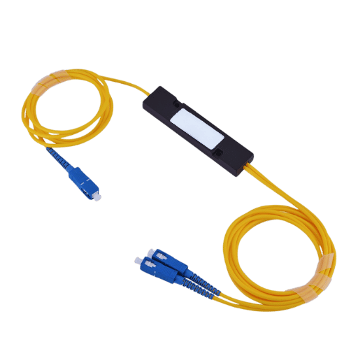
The two main types of splitters used in contemporary networks are Fused Biconic Taper (FBT) and Planar Lightwave Circuit (PLC) Splitters.
- FBT splitters incorporate older technologies, utilizing heat and stretching to combine optical fibers through a split. They are inexpensive and work well in networks with few splits, but they tend to fall below standards regarding uniformity in signal distribution.
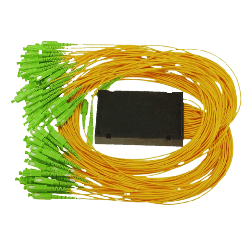
- PLC splitters employ sophisticated waveguide technologies, enabling them to distribute optical signals uniformly to multiple outputs. They are smaller, more reliable, and built for use in higher split ratio applications like FTTH (Fiber-To-The-Home) networks.
The most advanced of the two choices, PLC splitters tailored to dense modern networks offer superior performance and scalability. This proves yet again the mass adoption of modernization in network technology.
How to Choose the Right Fiber Optic Splitter for Your Network?
Factors to Consider When Selecting a Splitter
While picking a fiber optic splitter, pay special attention to the factors given below:
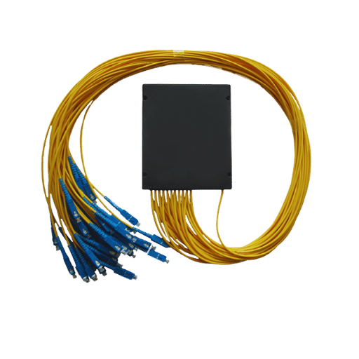
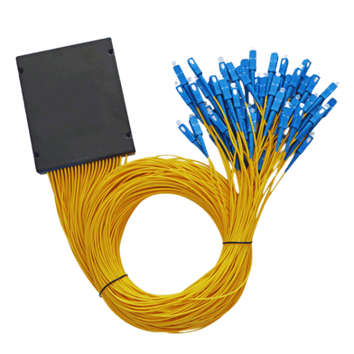
- Split Ratio Requirements: Determine the desired split ratio based on the number of outputs required to distribute the optical signal seamlessly. Shared network split ratios include 1X4, 1X8, 1X16, or higher.
- Network Type and Application: Define the communication network in which the splitter will be utilized, such as a passive optical network (PON) or FTTH deployment.
- Optical Performance: Analyze metrics like insertion loss, uniformity, and return loss, as these impact the network’s operational and signaling efficiency.
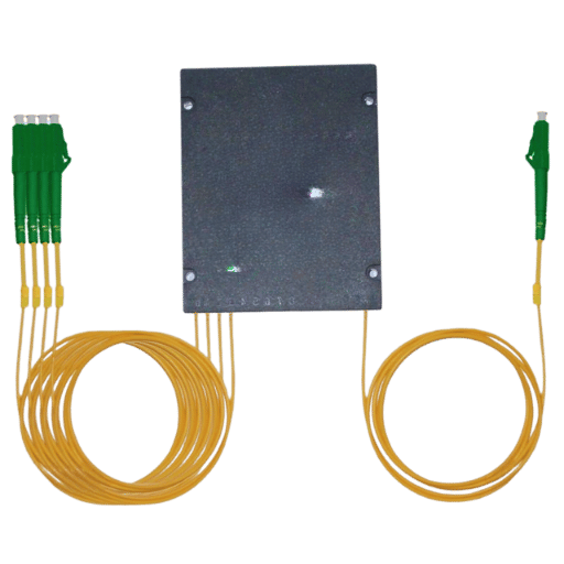
- Physical Configuration: Based on the design needs and installation space available, choose the preferred form factor, such as rack-mounted, bare fiber, or plug-and-play models.
- Environmental Conditions: Check if the splitter meets required environmental specifications like temperature range, moisture resistance, etc.
By clearly outlining these pointers, an appropriate splitter can be selected that best augments the network’s structure and performance.
Comparing Different Optical Splitter Models
The most vital metrics or parameters to consider in assessing optical splitter models are their splitting, design configuration, and insertion loss ratio.
- Splitting Ratio: Different models may have different ratio ranges, such as 1×2 or 1×4. Select a ratio that aligns with your network’s bandwidth distribution needs.
- Insertion Loss: Less insertion loss results in better signal quality; therefore, compare the models that offer minimal loss and better performance for your application.
- Design: Optical splitters, such as bare fiber and PLC splitter modules or rack-mountable units, can be configured differently. Choose the configuration that best suits the required space and deployment conditions.
Adhering to these parameters maximizes your chances of selecting a model that guarantees optimal performance and reliability while remaining integrated into your network infrastructure.
The Role of Output and Input Ports in Device Selection
The functionality and compatibility of an optical splitter in any given network will rely on how its input and output ports are arranged and their respective quantities. The input ports define the number of signals a splitter will accept, whereas the output ports outline how many resulting paths will be created from the split signal. A splitter with a port ratio corresponding to your network’s distribution requirements is best for performance. Configurations like 1×4, 1×8, or 1×16 are mainly for advanced growth and signal management. Striving for correct port configuration ensures minimal signal loss while maximizing network efficiency.
Can an Optical Splitter Affect Signal Quality?
Impact of Splitter on Optical Signal Integrity
Every time the optical splitter is used, each optical signal is weakened. This weakening is called insertion loss, a fundamental aspect of splitter operations that needs to be considered during network design. Good-quality splitters are designed to reduce insertion loss and provide uniform signal distribution at all ports, achieving uniform performance across all output ports. Regarding splitter type, network architecture, and range restrictions, appropriate calibration can reduce the expected harm to signal quality.
Minimizing Signal Loss in Fiber Optic Networks
Attention to detail in selecting and installing components is critical to reducing signal loss in fiber optic networks. To reduce attenuation, use low-attenuation optical fibers and trim all connectors, splices, and splitters to industry standards. Connection contamination and misalignment can yield degraded signals, so ensure connections are clean and properly aligned. The network’s design scheme should incorporate suitable power budgets, employing optical amplifiers as needed for prolonged transmission distances. Network signal integrity can be maintained through constant testing and maintenance.
What are the Applications of Optical Splitters in Audio Systems?
Exploring Digital Optical Audio Splitters
In contemporary audio systems, digital optical audio splitters are of prime importance due to their ability to effortlessly distribute digital audio signals from one source to several outputs. These devices capture and use TOSLINK (Toshiba Link) technology, an industry-standard optical fiber interface that conveys digital audio signals using light. This ensures minimal interference and high-quality sound reproduction.
As far as these splitters are concerned, linking television or gaming consoles to multiple devices such as soundbars, audio receivers, or home theater systems share a single audio source. Every two-way or four-way optical splitter can effectively preserve the bass frequencies alongside the original audio quality. Dolby Digital and DTS audio-compatible peripherals are also included in newer models, permitting use with advanced surround sound systems dedicated to immersive theater experiences.
Research suggests the optimal performance for telephone-grade optical fibers lies within the 10-meter range. Beyond this range, splitters experience output signal degradation due to increased distance. In parallel, lower-end 4 K-compatible televisions are being released, which provides more uses for these devices. This illustrates the relevance of digital optical audio splitters for high-definition entertainment systems.
When picking an optical splitter, users should prioritize models made with sturdy materials like metal and high-grade PVC to reduce the signal loss caused by mechanical wear. Some devices now integrate low latency technologies that enhance gaming or real-time audio streaming synchronization. Digital optical audio splitters, when pursued with an emphasis on their quality and compatibility, can streamline operational versatility within the audio framework.
Integrating Splitters with Soundbar Systems
Important guidelines must be followed when integrating optical audio splitters into soundbar systems. Modern audio devices such as soundbars support multiple input and output standards (formats), such as Dolby Atmos, DTS:X, and PCM. Hence, selecting a splitter that can help these audio standards is crucial. High-quality audio content splitters that boast 192kHz/24-bit audio support should be ideal due to their sound fidelity.
Equally important is the number of devices you plan to connect. Splitters with one or multiple ports are practical for a soundbar and home theater setup with gaming consoles and streaming players. They are available as 1×2, 1×3, 1×4, and more, which allows multiple outputs to be connected to a single source. Using splitter models with gold-plated connectors and advanced shielding can minimize the number of devices with audio devices.
All TOSLINK Cables can be universally supported, and signal quality with high-grade fibers is retained over distances of up to 10 meters. Users must also check that the splitter and soundbar support the same audio protocols to avert unsynchronized issues, particularly with formats like ARC (Audio Return Channel) or eARC. Observing these points ensures that splitters can boost audio performance in various home entertainment systems.
Benefits of Using Toslink Digital Optical Audio Splitter
Employing a Toslink digital optical audio splitter comes with many advantages, including:
- Multi-Device Audio Sharing: This allows a single audio source, such as a TV, to send a digital audio signal to multiple devices (e.g., a soundbar and headphones) simultaneously.
- Preservation of Audio Quality: Supports high-fidelity audio transmission with little to no signal interference or distortion, which means the sound will be clear and crisp.
- Reduction of Interference: Every cable uses an optical medium with no electromagnetic signal noise, which helps ensure that the audio signal remains constant and reliable over its entire duration.
- Ease of Installation: Toslink splitters are effortless to install; they do not require complex setup steps, making them convenient for most home entertainment systems.
With increased efficiency and excellent sound quality, a digital toslink fiber optical splitter can significantly improve audio setups.
How to Install and Maintain a Fiber Optic Splitter?
Step-by-Step Guide to Fiber Optic Installation
- Position the Splitter: Find a convenient location close to your audio source and target devices. Ensure the splitter is on a stable horizontal plane to avoid damaging or loosening the connections.
- Connect the Input: Ensure that a Toslink optical cable is connected on one end to the audio output port on your device, TV, or Audio Receiver, and the other side of the cable is then put in the splitter’s input port.
- Attach the Outputs: Use other Toslink optical cables to the devices you intend to connect, such as a Soundbar, headphones, or a home theater system, and connect them to the output ports of the splitter.
- Power the Splitter (if required): If your Toslink splitter does not come with power, use the provided adaptor to connect to an external power source and check if the power indicator is on.
- Test the Setup: Ensure that the audio source and all connected devices are powered on. Check whether audio is being transmitted to all intended outputs.
- Regular Maintenance: Use a dry, transparent cloth to gently wipe the splitter and the cable connections to prevent dust from them free of dust and debris. Wipe them down. Ensure that all the cables are not bent or twisted to help preserve their performance and longevity.
By following the steps above, users can optimally use the fiber optic splitters without interruptions.
Tips for Maintaining Your Network Equipment
- Keep Equipment Clean: Your devices should be dusted and cleaned periodically to maintain performance and prevent overheating. Avoid harsh chemicals, and wipe the exterior with a soft, dry cloth.
- Ensure Proper Ventilation: Avoid stacking or placing devices in confined spaces. Network equipment should be situated in adequately ventilated areas to prevent overheating.
- Update Firmware: Obtain the most recent updates and security patches from the manufacturer’s website.
- Inspect Cables and Connections: Inspect all cables and connectors. All connectors should be secure. Replace cables that show signs of wear or damage.
- Use Surge Protection: Employ surge protectors and uninterruptible power supplies (UPS) to safeguard equipment from surges.
- Monitor Performance: Regularly checking your network’s functionality and speed will help you spot problems early. If available, use network monitoring tools.
- Perform Regular Reboots: Periodic reboots of devices such as modems and routers can help maintain stability and resolve temporary issues.
Following the guidelines provided will help ensure the reliable performance of your network equipment.
Frequently Asked Questions (FAQs)
Q: What is the definition of a fiber optic splitter device, and what is its working principle?
A: Fiber optic splitters are elements in an optical fiber network that divide single optical signals into multiple signals for further processing. It splits the light beam by using a PLC splitter, which is a passive zone element, or it can be referred to as a power splitter, that redistributes the optical signals into different paths without external power.
Q: Can you tell me the difference between passive and active optical cable splitter?
A: Passive sc fiber splitters do not require an external power source to work and use natural properties of light to split the signal. In contrast, an active splitter employs command signals using an external power source, enabling greater control and amplification.
Q: In what way does a splitter 1 in 2 configuration assist a network?
A: Splitter 1 in 2 configuration splits a single optical signal into two signals. It improves the network by permitting better signal routing to several endpoints, which improves data accessibility and allows several instruments to share similar data simultaneously.
Q: Can a splitter be connected to a sound bar or other audio devices?
A: A Toslink splitter or a digital optical audio splitter adapter can be used with other equipment, such as sound bars. These devices help connect multiple audio outputs, enhancing the overall audio experience.
Q: What does an HDMI converter do, and what is its relation to a fiber optic splitter?
A: An HDMI converter connects an HDMI cable to different devices. While not directly considered a splitter fiber optic cable, it can be used with them to ensure that all digital signals passed through different cabling systems are sent correctly.
Q: Why is a digital optical audio splitter adapter necessary for home theaters?
A: A digital optical audio splitter adapter is essential for a home theater. It enables the audio signal to split and route to several devices, such as an amplifier or many speakers, ensuring that all channels produce high-quality sound.
Q: Do Fiber Optic Splitters Support Dolby Digital and DTS 5.1 Audio Formats?
A: Fiber optic splitters support Dolby Digital and DTS 5.1 audio formats. They help distribute high-grade digital audio signals to different devices without compromising the sound quality of the formats.
Q: What is the advantage of using a dual port toslink digital optical adapter in an audio system?
A: Dual port toslink digital optical adapter helps connect two devices to receive the same audio signal. This is useful for system design flexibility.
Q: What is the importance of a 1×3 spdif toslink optical splitter in professional audio?
A: A 1×3 spdif toslink optical splitter enhances the capability of simultaneously distributing a single digital audio signal into three audio devices, enabling seamless audio distribution through a Toslink fiber optical splitter 1, which is crucial in complex audio setups.
Q: In the context of fiber optic splitters, what does “LC compatible” mean?
A: “LC compatible” describes the connector style used in an optical fiber system. LC connectors are small, reliable, and favored in high-density network situations. LC-compatible fiber optic splitters ensure these devices can be integrated seamlessly into circuitry by employing LC connectors.
Reference Sources
1. Ultra-low Loss Multiport Optical Splitters
- Authors: Paloma Vildoso, R. Vicencio, Petrovic J
- Journal: Optics Express
- Date of Publication: March 7, 2023
- Citation Token: (Vildoso et al., 2023, pp. 12703–12716)
- Summary:
- This paper concerns problems in the inverse design of optical splitters, which involves creating designs with multiple functional parameters, such as arbitrary splitting ratios, low insertion loss, broad bandwidth, and compact footprint.
- The authors developed the Inverse Design Algorithm, a more efficient universal splitter design. They tested their method by assembling 1XN power splitters in borosilicate using direct laser writing.
- Key findings include:
- The splitters fabricated by the authors exhibit zero loss within experimental error and a competitive imbalance of less than 0.5 dB.
- The splitters’ bandwidth is configurable from 20 to 640 nm, and the splitting ratios are tunable between 60 nm and 640 nm.
- The throughput of the provided design algorithm is 100 times more than the traditional nanophotonic inverse design workflow.
2. Testing the Silica-based PLC Optical Splitters with an ‘In Situ Uniaxial Tensile Test’ Experiment Design
- Authors: Yu Zheng, Lianqiong Jiang, Jie Cheng, Jianzhe Liu, Ji’an Duan
- Journal: Applied Sciences
- Publication Date: June 07, 2022
- Citation Token: (Zheng et al. 2022)
- Summary:
- The work presented in this document studies the structural and optical features of silica-based planar lightwave circuit (PLC) optical splitters using uniaxial tensile loading.
- We fabricated an experimental test platform for a fiber-optic splitter, applying tensile loads while monitoring critical optical parameters, such as insertion loss (IL).
- Key findings include:
- The study marks the critical regions in the bonded fiber array-PLC chip interfaces.
- An empirical relationship between change in IL at 1.55 μm and the damage level of PLC optical splitters was formulated, which defined damage levels based on IL changes.
- This research builds a foundation for studying PLC optical splitter reliability design and damage mechanisms.
3. Design and analysis of 1 × 2N Y-branch optical splitters for telecommunication applications.
- Authors: S. Serečunová, D. Seyringer, H. Springer, F. Uherek
- Journal: Journal of Electrical Engineering
- Publication Date: September 1, 2020.
- Citation Token: (Serečunová et al., 2020, pp. 353–358)
- Summary:
- This paper outlines the design and optimization of 1 × 2N Y-branch optical splitters for specific purposes in telecommunications.
- The design incorporates a waveguide channel profile realized on a silica-on-silicon material platform.
- Key findings include:
- The design estimates insertion loss, non-uniformity, and background crosstalk for different Y-branch configurations.
- In each case, optimum Y-branch lengths were found concerning total insertion loss and non-uniformity of crosstalk.
- The results are helpful for the design of optical splitters dedicated to telecommunication systems.