The advancement of data transmission through fiber optics has completely transformed how we share and access data because of its unrivaled speed, reliability, and efficiency. At the cutting edge of this advancement is the single-mode LC connector, which acts as the link for network connectivity over long distances, enabling high performance. Whether you’ve been practicing in the telecommunication field or are a beginner wishing to hone your skills, mastery of the mechanics, benefits, and use cases of single-mode LC connectors is requisite. This guide will explain their functions, discuss the role of single-mode LC connectors in modern fiber optic systems, and present the logic for their adoption on a broader scale. After reading this article, you’ll appreciate the value of single-mode LC connectors in contemporary high-speed communication networks and understand why they’re essential.
What is a Singlemode LC Connector?
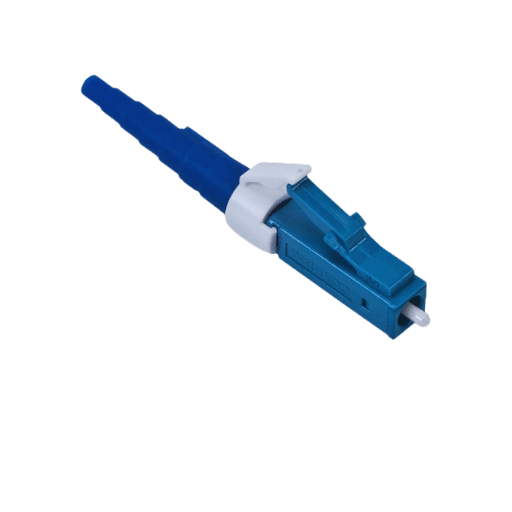
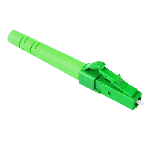
The Single Mode LC Connector is a high-efficiency and compact fiber optic converter crafted specifically for single-mode fiber optic cables. It possesses a 1.25 mm ferrule, which makes it perfect for snap-in, high-density, compact applications. Signal loss and interference are minimized with these connectors, making them beneficial for high bandwidth and long-range transmissions. Their accurate working and efficient light transmission make them incredibly trustworthy for telecommunications and data centers.
Features of LC Connector
- Space Efficient Compact Design: The LC connector’s compact design enables high port density which is useful for areas with limited space.
- Tighter Single-Mode Fiber Cables: The reduced ferrule diameter provides tighter single-mode fiber cables alignment, which reduces signal loss.
- Ease of Use Snap-In Mechanism: Connections can be made quickly and securely in a user-friendly way with the push-and-click design.
- Reduced Transmission Loss: The LC connector’s design is optimized to reduce transmission loss which allows reliable long distance and high-bandwidth data transfer.
- Stability Under Severe Force High Durability: Sustained robust performance designed connections remain stable in severe demanding applications.
How Does a Singlemode Fiber Connector Work?
The light signals can be transmitted through an optical fiber with minimal interference when its core is accurately molded into place, enabling the use of singlemode fiber connectors. Singlemode fibers have a core diameter of approximately 9 microns, which enables light to be transmitted into the fiber in a single propagation mode. This accurate interfacing prevents singular mode loss, which can lead to excessive attenuation over long-distance signal transfer.
Ceramic, steel, and sometimes even plastic make up the ferrules that are used to keep the core of the fiber in place during connection. These materials can absorb and reflect light at ranges close to none to enable proper alignment of the core itself. Also, other forms of polishing contact like physical (PC), ultra (UPC), and angled physical contact (APC) can further impede the signal reflection and optimize the output by working on the contact face of the ferrule.
Modern telecommunications set strict requirements for their networks; advanced singlemode connectors such as SC and LC are great as they support low insertion loss under <0.3 dB and over 50 dB for high return loss. These SMCs enhance bandwidth and reliable data transfer alongside the demand for high-speed internet, 5G networks, and data centers without losing crucial signal parameters. Furthermore, these attributes enable SMCs to support the ongoing demands for dependable data transfers and high bandwidth remote access.
Key Differences Between Multimode and Singlemode LC
- Core Size: Compared to singlemode LC fiber which has a core diameter of about 9 microns, multimode LC fiber has larger core diameters of 50 or 62.5 microns. This difference also changes how light propagates through the fiber.
- Signal Transmission: Multimode LC is more suitable for short distance communication while singlemode LC is designed for high-bandwidth long distance transmission.
- Wavelength: Singlemode fibers utilize longer wavelengths of 1310 nm and 1550 nm while multimode fibers operate at shorter wavelengths such as 850 nm and 1300 nm.
- Cost: Multimode LC systems are generally less expensive due to the lower cost of transceivers and connectors. Singlemode LC systems, although more expensive, outperform multimode systems over long distances.
- Applications: Commonly used in telecommunications and large-scale networking, singlemode LC is often the norm, while multimode LC is more prevalent in local area networks (LANs) and data centers.
How do you install an LC connector on a fiber optic cable?
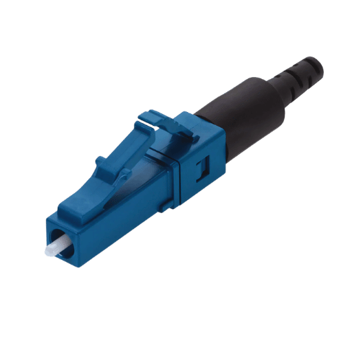
Step-by-step Installation Guide
Prepare the Fiber Optic Cable
- Carefully remove the jacket of the fiber optic cable to expose the fiber. Check that the fiber strands are clean and free of contaminants.
Trim the Fiber
- Create a smooth end on the fiber using a fiber cleaver to ensure maximum signal transmission.
Insert the Fiber into the Connector
- Place the fiber into the LC connector so that it fits the ferrule tip. It must be securely aligned in the connector to avoid misalignment.
Secure the Fiber
- Depending on the type of connector, adhere or mechanically crimp the fiber so that it is securely held in place.
Cure the Adhesive (If Applicable)
- If adhesive is used, allow it to cure as per the manufacturer’s instructions, ensuring a solid bond.
Polish the Connector
- With polishing film and proper tools, polish the ferrule end until smooth and reflective.
Inspect the Connection
- Using a fiber optic inspection microscope, check the quality of the connection for scratches or visible debris.
Test the Fiber Link
- Validate network transmission quality via a fiber optic power meter, checking that the installation performs to specifications.
Reliable network performance depends on the precision steps taken during LC connector installation.
Tools Required for Terminating LC Connectors
Equipping the following tools and equipment aids in the proper termination of LC connectors and ensures optimal results; each tool aids in achieving reliable connections:
Fiber Optic Stripper
- These scissors remove the protective coating of optical fiber without scratching the inner glass core. Always make sure these tools are designed for specific diameters of the fibers being terminated.
Cleaver
- For low-loss splicing or connectorization, a clean and accurate cut to the fiber end is needed, hence a precision fiber cleaver is critical. Most high-performance cleavers achieve a cleave angle of < 0.5degree, which is regarded as the best.
Connector Ferrules and LC Housing
- These components of higher grade LC connectors, ferrules, and other structures made of ceramics need to be made so that there is no misalignment, and light transmission is done without the wastage. Always ensure the connectors correspond to the cable’s type (multimode or single-mode).
Epoxy or Adhesive Kit
- The adhesive or epoxy need is omnipresent in regard to holding the fiber inside of the connector. Make sure these are fast curing and most importantly compatible with the operating environment and temperature.
Crimping Tool
- These are used to fasten the connectors to the fiber cable. Changeable crimpers are most suitable, since they apply the correct amount of force that will avoid damaging the structure, but still allow a strong mechanical connection.
Tools and Consumables Polishing
- Use a polishing fixture with a lapping film or polishing pad to achieve end-face finishes that have an insertion loss and back reflection of ≤ -40 dB. For repetitive tasks, automated polishing machines are ideal for large-scale operations.
Cleaning Kit
- It includes lint-free wipes, isopropyl alcohol, and fiber optic cleaning fluid to ensure that surfaces are clean before and after termination. Cleaning pens are also useful for the internal cleaning of the connector.
Inspection Scope
- Scratches, pits, and any other form of contamination are monitored using fiber optic inspection microscopes. Digital models that save inspection images are more efficient for documentation in quality assurance workflows.
Testing Tools
- A pair of fiber optic power meter and light source, or an Optical Time-Domain Reflectometer (OTDR) tests the quality of the terminated link. These gadgets test insertion loss, return loss, and the overall integrity of the link.
Heat Oven (If Needed)
- For connectors with heat-cured epoxy, a curing oven makes sure the adhesive sets accurately. Always adhere to the instructions of the manufacturer to avoid overheating the fiber.
The right tools will enable you to understand how to apply them correctly, allowing the termination process to achieve the desired industry standards of quality and reliability. Having a systematic approach to proper tool maintenance, including periodic calibration and cleaning, enhances tool performance over time.
Common Installation Mistakes to Avoid
Failure to Clean Fiber Properly
- Cleaning or not cleaning at all using incorrect techniques can result in lost signals or damage to the connectors. To prevent these issues, use all designated cleaning solutions and lint-free wipes.
Bending Cables Too Much
- Going past the minimum required bending radius can cause stress to be put on the fiber which results in the impairment of micro-cracks or performance. Follow manufacturers’ instructions for handling with care.
Ignoring Inspections of Connectors
- Not checking the connectors for scratches, grime, or any form of damage that might happen during the installation can lead to all forms of faulty connections. Use a fiber inspection scope to check the connector’s cleanliness.
Transmitting And Receiving Signals In The Wrong Order
- Transmitting and receiving signals through fibers twisted in the wrong order results in signal interference. Check the polarity settings based on the system layout before conducting final assembly.
Using Wrong Tools
- Marked tools that are uncalibrated pose a risk to the termination process. Ensure that all tools provided are in good working condition, valid standards, and are operational before engaging them.
With the neglect of these basic problems, installation output will be improved aseptically, increasing the performance and lifespan of the system.
What are the Benefits of Using Fiber Patch Cables with LC Connectors?
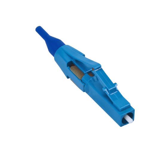
Advantages of LC Fiber Patch Cables
Compact Connector Size
- LC connectors have a Small Form Factor (SFF) design which allows for compact port arrangements. They are ideally suited to densely packed network environments, such as data centers because they take up around 50% less space than SC connectors.
Low Insertion Loss and High Return Loss
- LC fiber patch cables have exceptional performance with insertion loss values between 0.10 dB and 0.30 dB. Their return loss is also high, exceeding 50 dB, which ensures minimal signal reflection and maintains signal integrity in high-speed networks.
Ease of Installation and Maintenance
- Installation and removal of LC connectors is made easier due to the latch style mechanism. This improves the likelihood of fiber being undamaged during handling and aids in deployment and routine maintenance activities.
Wide Compatibility
- Support for LC connectors is quite broad among various equipment such as optical transceivers, modules, and patch panels making these connectors versatile and scalable for many network applications.
Enhanced Network Performance
- Due to low optical loss and precise alignment, signal transmission efficiency is bolstered, making LC fiber patch cables ideal for high-bandwidth applications like 40G/100G Ethernet and beyond.
Durability and Reliability
- LC fiber patch cables are made with strong materials that can endure rigorous operational environments. Most include advanced features such as reinforced boots that alleviate stress at connection points, maintaining reliability over time.
With these advantages, LC fiber patch cables provide efficient, high performing, and scalable solutions to modern fiber optic networks.
Performance Metrics: Insertion Loss and Return Loss
Insertion loss and return loss are some of the most important performance measures for assessing the quality and performance parameters of fiber optic network parts LC fiber patch cables.
Insertion Loss
Insertion loss defines the value of loss in optical signal power in a fiber optic connection when it is traversing through the connection. Insertion loss is expressed in terms of decibels (dB) in fiber optics. Greater performance is indicated by a lower value of insertion loss. Industry standards recommend values under 0.3 dB for high-quality single-mode fiber connections and under 0.5 dB for multimode fibers. Some of the factors contributing to insertion loss are poor connector alignment, core mismatches, and other physical imperfections. Connectors should be regularly cleaned to ensure proper alignment, which is essential to minimize insertion loss.
Return Loss
Return loss measures the amount of light that is reflected back toward the source because of discontinuity in connection or impedance mismatch. Return loss is also in the form of decibels, but unlike insertion loss, greater values indicate better performance. The aim of modern fiber optic systems is to achieve return loss values of 50dB and above for single-mode fibers and 20dB and above for multimode fibers to ensure minimum signal distortion and interference.
High-precision LC connectors are instrumental in maintaining optimal extrusion and return loss values, and as an example, tactile ultraprecise contact (UPC), as well as angled physical contact (APC) polished connectors, tend to perform better because of less reflection and better alignment. Preserving these metrics is important to sustain the requirements of fast networks and guarantee the reliability of signals in various applications like data centers, telecommunication works, and enterprise networks.
How do Maintain and Specify LC Connectors for Optimal Performance?
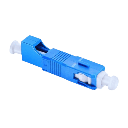
Cleaning and Care of Fiber Optic Connectors
Connector cleanliness is crucial to guarantee the best performance and signal quality, and maintenance cleaning is equally important. The presence of dust, oil, or other debris on the surface of a connector can result in signal attenuation or damage. In order to clean fiber optic connectors:
- Employ Proper Cleaning Equipment: Use lint free cloths or fiber optic cleaning pens made for these specific connectors. Tissues and cotton swabs should be avoided since they originate from household.
- Check Both Pre and Post-Clean: Prior to reconnection, verify with a fiber scope inspection scope that the area cleaned is indeed clean.
- Restraining from touching the ferrule: The ferrule end face is prone to contamination. Therefore, retraction from touching the end part of the connector is advised, and the connector body should always be used.
- Put Connectors In Correct Storage: When dust caps are out of use, the end of the connectors should be sealed so as to ensure that no contaminants go in.
Coverage of the above ensures that maintenance issues will hardly arise, while the effectiveness of the existing fiber optic connections will last much longer.
Choosing the Right Specifications for Your Needs
With optics, we must remember the factors relevant for a specific application as these are very important for the performance and reliability of fiber optic systems. Other than requiring careful performance calculations, they also require opt for grade considerations such as environmental conditions, bandwidth, and transmission distance.
- Bandwidth and Data Rate Requirements: What is the anticipated transfer of data for a specific network? Single mode fibers provide support for long distance transfer of data iterating over 400 meters at a pace greater than 100 Gbps. Multimode fibers, on the other hand, aid in short distance communication which single mode does not cover.
- Transmission Distance: How does the signal radius need to be extended? Single-mode fibers are most suitable for extension exceeding 10 kilometers as signals for multiline emissions and absorption eat away at signal attenuation and dispersion. For short distances, the low-level addition of multi-mode fibers provides support.
- Core Diameter and Mode: Ranging from 50 micrometers to 62.5micrometers, multimode fibers possess higher core diameters while multi mode offer cores near 9micrometers for single light emission. This necessity allows for low interference on senors over large distances.
- Environmental Tolerance: If there is movement through delicate areas, a harsh environment requires outdoor-rated cables that are protected against damage such as water and temperature extremes. The UL is capable of providing better durability when adverse conditions are present through jacketed cables.
- Connector Types and Compatibility: Verify that all of your system components are tailored to the appropriate connection type. LC, SC, and MPO connectors should be compliant with both the physical and operational capabilities of your infrastructure.
- Cost vs. Performance: Correspond cost with performance by evaluating total lifecycle cost, as all expenditures contribute to asset value in the unit’s operational context. For instance, single mode systems may be more expensive at first, but offer lower upkeep costs than multimode systems when deployed for long distance purposes.
Considering these factors makes it easy to select fiber optic components that help achieve operational requirements within set financial constraints. Understanding your network’s intended application helps in ensuring adequate performance and scalability in the long run.
What are the Specifications and Standards for LC Fiber Connectors?
Understanding OS2 and OM1 Ratings
While looking into LC fiber connectors, it is very important to know what OS2 and OM1 ratings are, as they have a direct impact on relevant solutions for given tasks. Such ratings determine the scope, functionality, limits, and compatibility of the fibers in relation to their core size, range of transmission, and maximum bandwidth.
OS2 Fibers
OS2 (Optical Single Mode 2) fibers are appropriately used for long-haul transport as they tend to work best at wavelengths 1310 nm and 1550 nm. Their core size is small, about 9 µm, and consists of strands optimized for the lowest possible sending of signals, having an average attenuation rate of about 0.4 dB/km at 1310 nm and 0.25 dB/km at 1550 nm. OS2 fibers are well suited for outdoor applications having distances in excess of 10 km, like metropolitan or core network infrastructure. With higher precision they can transmit data, therefore are well suited for modern systems using dense wavelength division multiplexing (DWDM).
OM1 Fibers
As multimode fibers, OM1 (optical multimode 1) fibers have a core size of 62.5 µm. They are commonly employed in applications with shorter distance requirements. OM1 fibers transmit within a wavelength range of 850 nm to 1300 nm. Their bandwidth capacity is 200 MHz·km at 850 nm and 500 MHz·km at 1300 nm, typically being deployed for essential networks or systems up to 300 meters. These fibers are less expensive and more appropriate for local area networks (LANs) and other indoor applications.
Technical Comparison
To tell them apart, OS2 fibers emphasize low attenuation for high-performance long-distance data transmission, while OM1 fibers are more cost-effective for limited-range applications. OS2 has a smaller core to reduce modal dispersion, and OM1 has a multimode design that enhances compatibility with older light sources like LEDs. In making choices, the maximum transmission distance, required bandwidth, and environmental conditions need to be factored in.
Strategically aligning the fiber rating to network requirements enables optimal performance and cost savings when constructing or upgrading optical fiber networks.
Differences Between Simplex and Duplex LC Cables
The distinction between simplex and duplex LC cables lies mainly in their configuration and use:
- Simplex LC Cables: These are made up of one fiber only, which allows for one-way data transfer. They are generally employed in systems where data transfer is one-way only (for example, certain types of sensors or one-way communication systems).
- Duplex LC Cables: These have two fibers within them, allowing transmission and reception of data simultaneously in both directions. These are mostly used in other network related activities like data center communications and telecommunication which need two-way data transmission.
The selection of simplex or duplex will depend on the actual use case of the network or application.
Frequently Asked Questions (FAQs)
Q: What is a single-mode LC Connector?
A: A Single Mode LC Connector is a type of connector designed to terminate single mode fiber cables because of its compact size. Like other connectors, it facilitates the connection and disconnection of fiber optic cables.
Q: How does a Single Mode LC Connector differ from SC and ST connectors?
A: The Single Mode LC Connector is smaller than SC and ST connectors, offering a space saving design. Its latch mechanism resembles that of an RJ-45 while SC connectors use push-pull coupling and ST connectors use bayonet mounts. For these reasons, they are preferred in high density environments where low loss and precision are required.
Q: What are the key components of an LC connector fiber system?
A: Components of an LC connector fiber system includes LC connectors, fiber optic cables, fiber stubs, dust caps, mountable enclosures, etc. These all serve to uphold a dependable fiber optic connection with minimal data loss.
Q: What are the fire safety regulations for the use of plenum-rated LC Connectors?
A: Any work performed in air-handling spaces, such as in drop ceilings or raised floors, must abide by specific fire safety standards. These standards are met with the use of plenum rated LC connectors. They withstand fire better than OFNP rated fiber optic components which are purposefully designed to lessen the emission of dangerous smoke which is essential for the safety of building infrastructure design.
Q: Is it possible to use single-mode LC Connectors with multimode Om1 fibers?
A: Single mode fiber connectors are not meant for multimode OM1 fibers, but there are multimode LC connectors made for OM1 and other multimode fibers to ensure seamless integration and effectiveness within fiber optic systems.
Q: In what ways does the fusion splicer augment the installation procedures of LC singlemode connectors?
A: The tool known as the fusion splicer is specifically utilized in the optical telecommunications industry. It guarantees a low loss of optical fiber connection, a highly important factor for maintaining a smooth signal pathway. This quality tool augments the integration of sophisticated electronics, such as the LC singlemode connectors, by effortlessly performing robust joints without affecting the transmission quality, an important requirement in professional caliber fiber optic installations.
Q: Why is it beneficial for LC singlemode connectors to be associated with a fiber optic splice?
A: It is reasonable to state that fusion splices such as the one used in LC singlemode connectors serve the purpose of creating seamless unions between fiber optic cables. This will allow the achieved communication links to further span across larger distances at much higher speeds. Such sleek operations are purely essential when discussing the capabilities of modern-day fiber optic networks.
Q: Are there any particular tools or apparatuses necessary for the rest of the LC connectors to be assembleable in the field?
A: Field installable LC connectors come with their own specific range of tools and accessories offset such as pre-polished fiber stubs (PC connectors), pigtails or low loss pigtails, mechanical splicing tape, and even custom protective trays or tubing designed to support and hold the splice in place for a dependable connection.
Q: Where can I find more information about LC singlemode connectors?
A: Suppliers and manufacturers that deal with fiber optics technology have specialized product pages that contain more information about singlemode LC connectors. Such pages usually provide detailed documentation like specifications, manuals, checklists for installation, and other custom options tailored to different levels of connectivity.
Reference Sources
1. Single-Mode 24-Fiber Connector With GI Fiber Lens Array
- Authors: O. Shimakawa et al.
- Publication Date: March 22, 2015
- Journal: Optical Fiber Communications Conference and Exhibition
- Citation Token: (Shimakawa et al., 2015, pp. 1-3)
- Summary: This paper describes a single-mode 24-fiber connector with graded index (GI) fiber lenses and MT-connector based guide-pin alignment. The study reported an average insertion loss of 0.54 dB and loss variation of less than 0.08 dB due to temperature cycling illustrating the design’s ability to perform consistently across varying conditions.
2. Single-Mode 32-Fiber Connector With GI Fiber Lens Array
- Authors: H. Arao et al.
- Publication Date: April 20, 2015
- Journal: IEEE Optical Interconnects Conference
- Citation Token: (Arao et al., 2015, pp. 118-119)
- Summary: This paper covers the design of a single-mode 32-fiber lensed connector where the average insertion loss was 1.0 dB and return loss was greater than 30 dB. The design is based on a non-coaxial optical design, not only improving performance but also increasing robustness for optical interconnects.
3. Single-mode small-form-factor fiber optic connectors for use in enterprise computing systems
- Author: C. DeCusatis
- Year of Publication: 2002
- Journal: Optical Engineering
- Citation Key: (DeCusatis, 2002, pp. 2438–2447)
- Abstract: This paper describes a novel strain relief design for high-density I/O interconnects that can substitute SC Duplex interfaces in multimode and single-mode applications. The study also includes performance comparison and stress analysis of a number of tested connector types, focusing on the appertaining mechanical stress tests.
4. Optical fiber connector
5. Optical fiber
6. Electrical connector
Post Views: 5,543


