In 2024, Marcus Chen and his network engineering team at a mid-sized cloud services company faced a critical infrastructure decision. Their AI workloads demanded 400G spine switch upgrades, yet the data center still had 800 servers equipped with 100G NICs. Replacing all endpoints would cost $2.4 million and require six months of scheduled downtime. Instead, Marcus deployed QSFP-DD breakout cables to split each 400G spine port into four 100G connections. The entire migration was completed in just three weeks with zero service interruptions, and the total cable cost remained under $50,000.
The current situation demonstrates that QSFP-DD breakout cable and 400g breakout cable technology has become a fundamental requirement for contemporary data center development. Organizations that adopt 400G and 800G infrastructure benefit from breakout cables, which serve as an economical solution, linking their new high-speed switches to current 100G endpoints. The guide provides network engineers with information about breakout technology and cable selection and deployment strategies, which they can use to plan their upcoming infrastructure upgrades.
What is a QSFP-DD Breakout Cable?
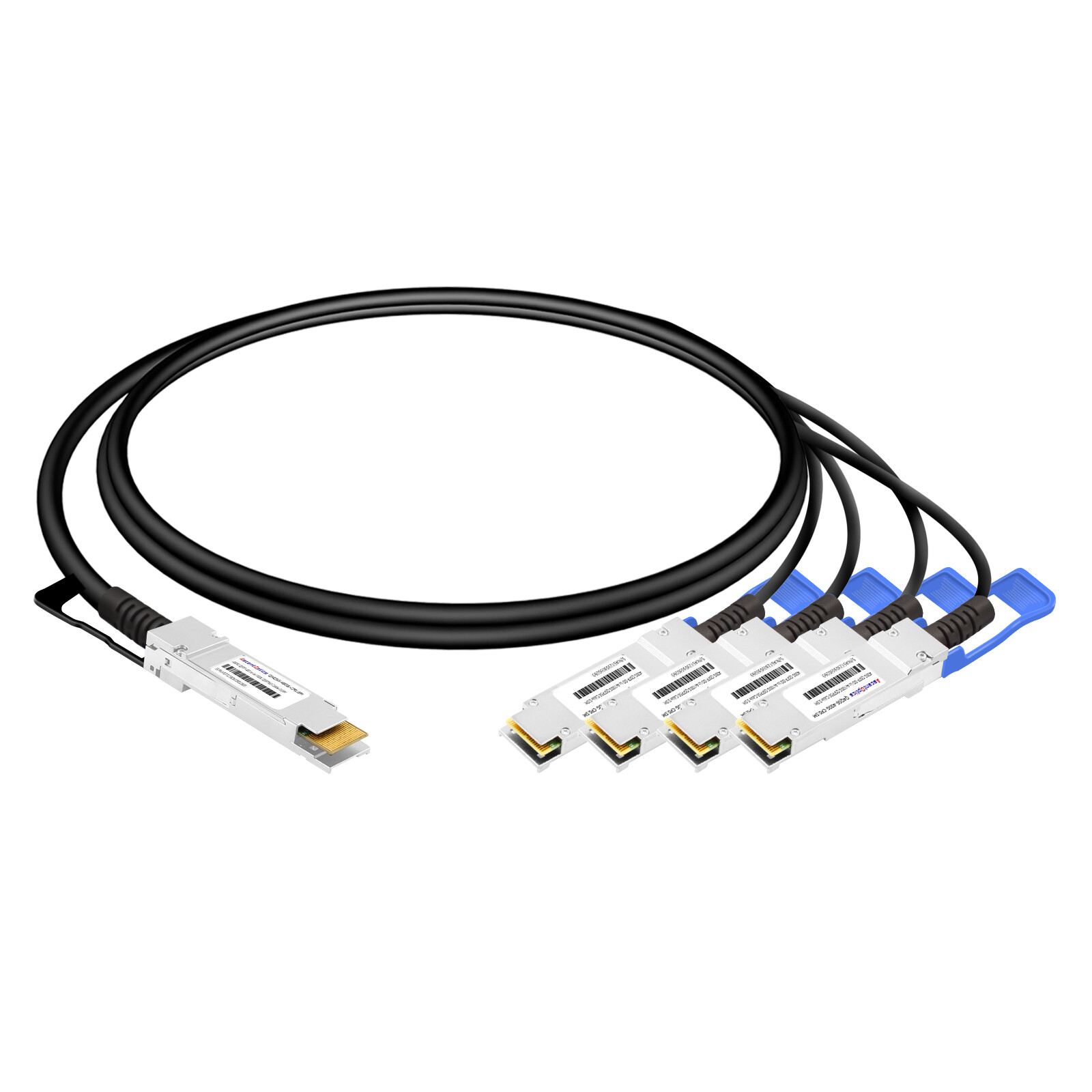
A QSFP-DD breakout cable establishes a dedicated cabling system which enables multiple lower-speed connections from one high-speed QSFP-DD port. The breakout cables permit a 400G port to establish connections with four 100G endpoints which enables better port usage during migration times.
Breakout Technology Fundamentals
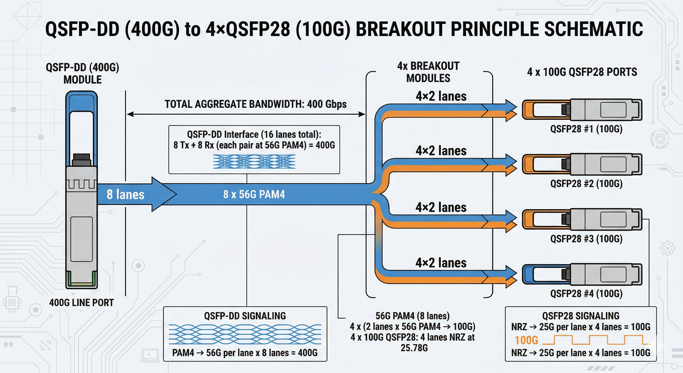
The standard QSFP-DD modules achieve 400 Gbps transmission through eight electrical lanes which operate at 50 Gbps using PAM4 modulation. The breakout cables divide the eight lanes into four distinct connectors which receive two lanes each to create 100 Gbps connections.
The cable uses either passive copper traces or active signal-processing electronics to handle lane mapping internally. This allows administrators to connect modern 400G switches directly to legacy 100G equipment without external muxponders or protocol converters.
Lane Mapping and Gearbox Technology
Understanding lane distribution helps clarify how 400G to 100G breakout and QSFP-DD breakout applications work in practice. A QSFP-DD port uses the following lane structure:
| QSFP-DD Lane |
Breakout Port
|
Assignment
|
| TX1/RX1 (Lane 0/1) |
Port 1
|
100G signal
|
| TX2/RX2 (Lane 2/3) |
Port 2
|
100G signal
|
| TX3/RX3 (Lane 4/5) |
Port 3
|
100G signal
|
| TX4/RX4 (Lane 6/7) |
Port 4
|
100G signal
|
Active breakout cables include internal gearbox chips that manage signal timing and ensure proper synchronization between the 400G host port and 100G endpoints. The operation of passive breakout cables depends on direct copper traces which only provide functionality within extremely limited distances that maintain signal integrity.
Common Breakout Configurations
Modern data centers deploy several QSFP-DD breakout applications depending on their infrastructure requirements:
400G to 4x100G (Most Common)
- •Splits one 400G QSFP-DD into four 100G QSFP28 or QSFP56 connections
- •Ideal for spine-to-leaf connectivity during migration
- •Supported by most enterprise switch platforms
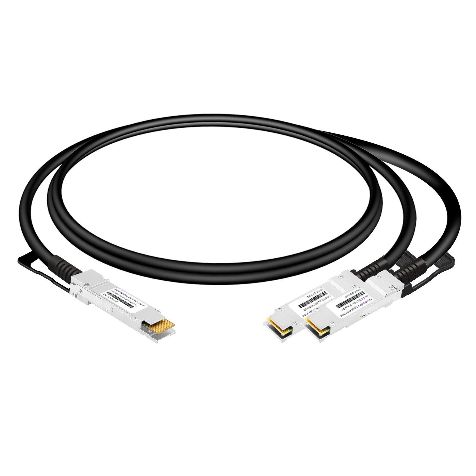
400G to 2x200G
- •Divides 400G into two 200G QSFP56 connections
- •Useful for high-bandwidth aggregation scenarios
- •Emerging standard for dense computing environments
800G to 2x400G
- •Splits 800G QSFP-DD into two 400G connections
- •Enables high-speed spine interconnects
- •Forward-looking configuration for next-generation networks
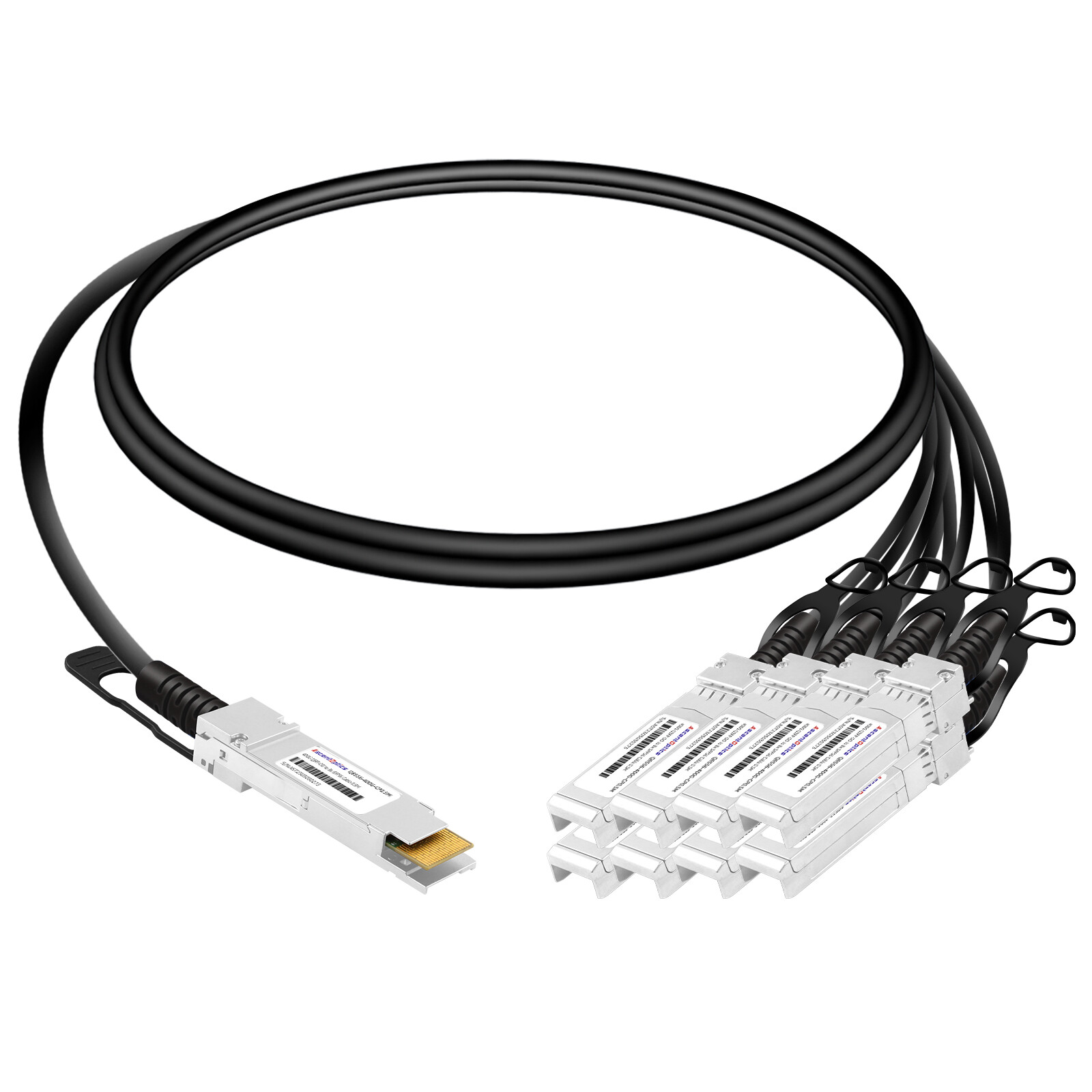
800G to 8x100G
- •Maximum fanout configuration for GPU cluster connectivity
- •Provides highest port density expansion
- •Requires specialized cabling infrastructure
QSFP-DD Breakout Cable Types
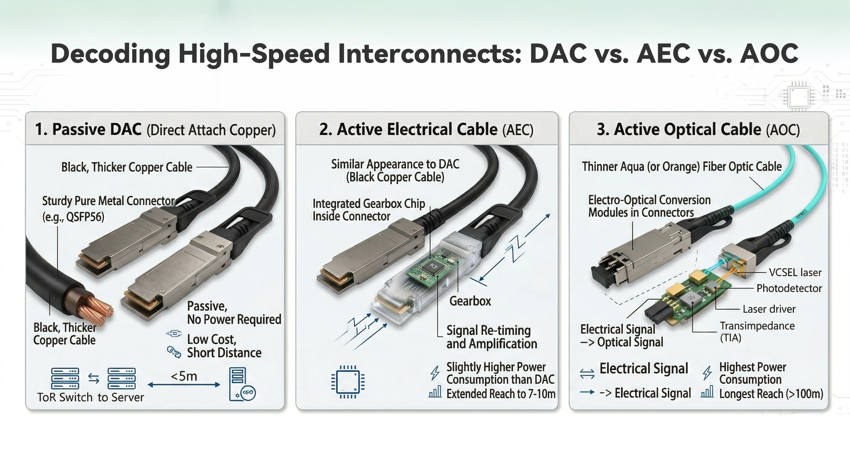
Selecting the right QSFP-DD breakout cable for your 400G breakout cable installation depends on distance, power constraints, and signal quality requirements. The three main technologies offer distinct deployment advantages.
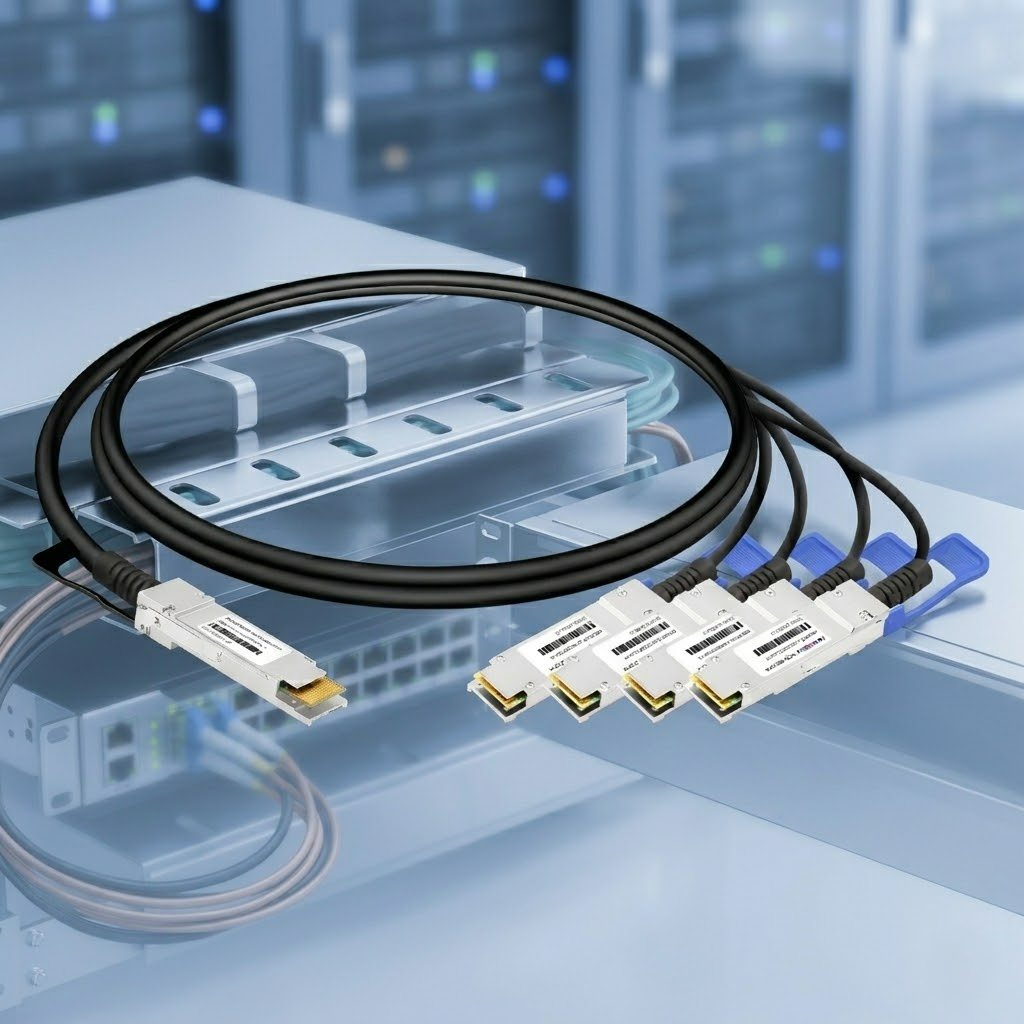
Passive DAC Breakout
Passive Direct Attach Copper (DAC) breakout cables provide the simplest and most cost-effective solution for short-reach connections.
Technical Specifications:
- •Maximum reach: 1-3 meters
- •Power consumption: <1.5W total
- •Signal type: Direct electrical connection
- •Cost range: $50-150 per cable
The passive DAC breakout cables use only passive components because they do not include any active electronic parts. The system maintains its signal quality because it uses twinax copper cables which have exact impedance matching properties to create a high-quality connection. The cable assembly includes the QSFP-DD connector on one end and four QSFP28/QSFP56 connectors on the other, with internal traces handling the lane mapping.
Best Applications for Passive Breakout DAC:
- •Top-of-rack switch to server connections within the same rack
- •Leaf-to-spine connections where switches occupy adjacent rack units
- •Cost-sensitive breakout DAC vs AOC comparison scenarios with short cable runs
Engineering Note: When deploying passive DAC breakout cables, verify that your switch platform supports breakout mode on the specific ports. Some switches require software configuration to enable 4x100G breakout operation on QSFP-DD ports.
For organizations evaluating passive DAC options against other cable types, our QSFP-DD power consumption guide provides detailed power efficiency analysis.
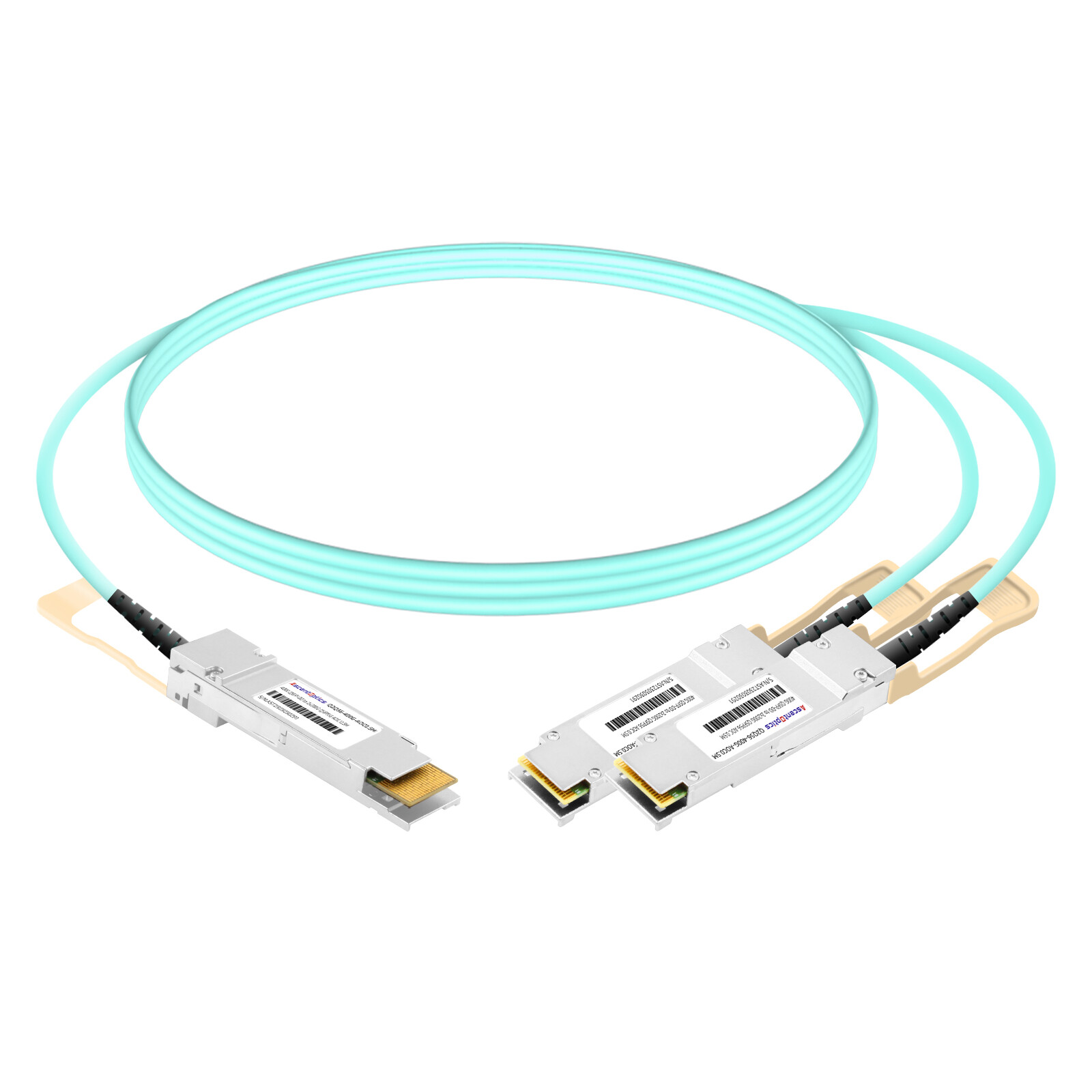
Active AOC Breakout
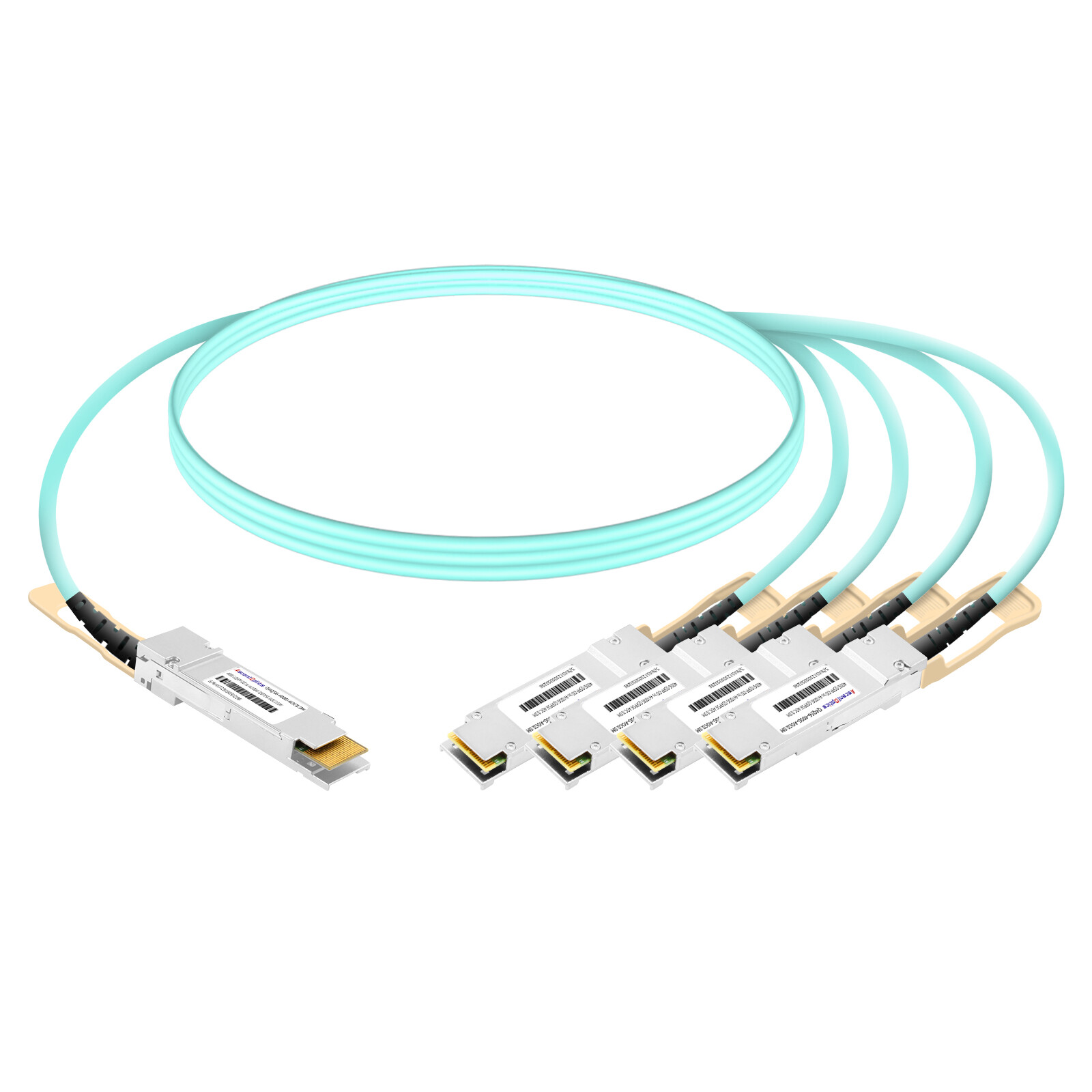
Active Optical Cable (AOC) breakout cables use fiber optic technology with integrated transceivers to extend reach beyond copper limitations.
Technical Specifications:
- •Maximum reach: 1-30 meters (model dependent)
- •Power consumption: ~10W at QSFP-DDend, ~5.5W per 100G end
- •Fiber type: OM3 or OM4 multimode
- •Cost range: $500-1,200 per cable
The AOC breakout cables handle electrical signal conversion through the QSFP-DD connector which sends signals through parallel fiber ribbons and performs electrical signal conversion at each 100G connector. The system achieves extended transmission distances through active signal conversion which preserves the quality of the transmitted signals.
Modulation Compatibility Considerations:
| 400G Side |
100G Target |
AOC Requirement |
| DR4/FR4 (PAM4) |
QSFP56 PAM4 |
Standard AOC |
| DR4/FR4 (PAM4) |
QSFP28 NRZ |
AOC with gearbox |
| SR8 (PAM4) |
QSFP56 PAM4 |
MPO breakout variant |
Modern AOC breakout cables include built-in gearboxes that handle PAM4 to NRZ conversion when connecting to legacy QSFP28 modules that use NRZ modulation. The system needs this compatibility feature to enable new 400G infrastructure operation with existing 100G equipment.
Best Applications:
- •Inter-rack connectivity in data center rows
- •Spine-to-leaf connections spanning multiple meters
- •Environments requiring electromagnetic interference immunity
Active Electrical Cable (AEC) Breakout
Active Electrical Cables (AEC) represent an emerging category that combines the cost advantages of copper with active signal conditioning for improved performance.
Technical Specifications:
- •Maximum reach: 1-5 meters
- •Power consumption: ~4.5W per end
- •Signal processing: Active equalization and retiming
- •Cost range: $150-400 per cable
AEC breakout cables use signal conditioning chips which eliminate noise and boost signals without changing the original optical signals. The system achieves superior signal integrity through its active DAC method which operates at short distances while using less energy compared to AOC solutions.
Key Advantages:
- •Signal integrity superior to passive DAC
- •Lower power consumption than AOC
- •No fiber handling or cleaning requirements
- •Better PAM4 signal stability for high-speed applications
NVIDIA and AI Cluster Applications:
AEC breakout cables have become popular in AI training clusters which use NVIDIA GPUs. The cables support the specific signal timing and FEC requirements which high-performance computing environments require to maintain their essential low latency performance.
Cable Type Comparison Matrix
| Specification |
Passive DAC
|
AEC |
AOC
|
| Maximum Reach |
1-3m
|
1-5m |
1-30m
|
| Power per Cable |
<1.5W
|
~9W |
~10W
|
| Relative Cost |
Lowest
|
Medium |
Highest
|
| Signal Integrity |
Basic
|
Enhanced |
Excellent
|
| Fiber Required |
No
|
No |
Yes (OM3/OM4)
|
| Best Use Case |
Same-rack ToR
|
ToR/Adjacent rack |
Inter-rack spine-leaf
|
MPO Connector and Polarity for Breakout Cables
Optical breakout cables rely on Multi-fiber Push-On (MPO) connectors for parallel fiber transmission. Proper MPO configuration is essential for correct signal flow.
MPO-12 vs MPO-16 Connectors
Two MPO connector variants dominate high-speed networking:
MPO-12 (12-Fiber)
- •Contains 12 fiber positions in single row
- •Typically uses 8 active fibers (4 TX, 4 RX)
- •4 unused fibers provide spare capacity
- •Standard for 400G SR8, DR4, and FR4 modules
MPO-16 (16-Fiber)
- •Contains 16 fiber positions (8 top, 8 bottom)
- •All 16 fibers active in 800G applications
- •Required for 400G SR8 and 800G SR8/DR8
- •Forward-compatible with next-generation standards
The industry standard connector for 400G to 100G breakout applications through QSFP-DD to 4x100G optical breakouts with SR8 modules uses MPO-12 connectors. The 8-fiber array provides two fibers to each 100G breakout leg which results in four distinct 100G connections.
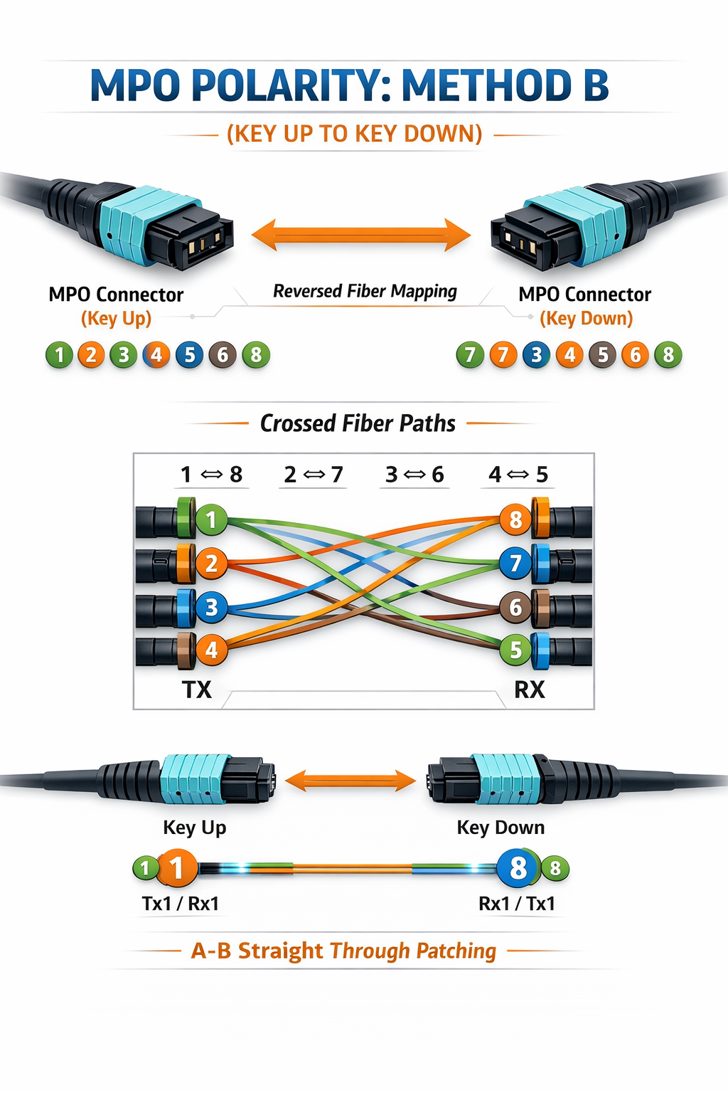
Method B Polarity (Crossover)
MPO polarity defines how transmit and receive fibers align between connected devices. Method B polarity has become the industry standard for 400G and 800G parallel optics.
Method B Configuration:
- •Key-up to key-down connector orientation
- •Fiber 1 on first connector maps to fiber 12 on second
- •Creates natural crossover between TX and RX fibers
- •Required for SR8, DR4, DR8, and FR8 modules
Deployment Warning: Using incorrect polarity causes complete link failure. Always verify polarity before deploying MPO-based breakout cables. Simple polarity testers can verify configuration in seconds and prevent hours of troubleshooting.
Polarity Verification Steps:
- •Inspect connector keys and orientation
- •Verify key-up to key-down mating for Method B
- •Use visual fault locator to confirm fiber mapping
- •Document polarity method in cable labeling
APC vs UPC Polish
Fiber end-face polish type significantly impacts 400G/800G performance:
APC (Angled Physical Contact) – 8° Angle
- •Mandatory for 400G/800G parallel optics
- •Return loss: <-60 dB
- •Green connector housing identifies APC
- •Reduces back reflections that cause signal interference
UPC (Ultra Physical Contact) – Flat Polish
- •Return loss: <-50 dB
- •Blue connector housing identifies UPC
- •Acceptable for lower-speed applications
- •Not recommended for 400G breakout deployments
Using UPC connectors in 400G breakout applications causes excessive return loss, resulting in bit errors and potential link instability. Always specify APC polish for breakout cable deployments.
MPO Gender and Connection Best Practices
MPO connectors come in male (with alignment pins) and female (without pins) variants. Proper gender pairing prevents connector damage:
| Component |
Typical Gender |
Notes |
| QSFP-DD Transceiver |
Male |
Contains alignment pins |
| MPO Cable Connector |
Female |
Receives pins |
| MPO Patch Panel |
Female |
Standard for structured cabling |
| Fanout Cable |
Male to LC |
Breakout to duplex connections |
Rule: Always mate male to female. Never force two male connectors together, as this damages alignment pins and renders connectors unusable.
Deployment Scenarios and Use Cases
QSFP-DD breakout cable technology serves diverse infrastructure requirements across modern data center architectures.
Spine-Leaf Architecture Integration
Breakout cables play a critical role in spine-leaf network designs during capacity expansion:
Leaf Access Fanout:
A single 400G spine port can feed four 100G leaf switches using breakout cables. The system design achieves optimal port usage while establishing multiple redundant connections to the leaf layer. Network operators are able to perform gradual leaf switch upgrades from 100G to 400G during migration periods without needing to change spine connections.
Oversubscription Management:
Spine-leaf networks typically operate with 3:1 oversubscription ratios for general computing workloads. The use of breakout cables allows precise tuning of oversubscription through the capability to use partial port capacity. The 400G spine port supports three active 100G leaf connections together with one spare port which creates a 3:1 oversubscription ratio until native 400G leaf switches become operational.
A hyperscale data center deployed 32-port 400G spine switches through breakout cables which connected 128 100G leaf switches. The existing cable system supported 400G speeds after leaf switches upgraded their compatibility from 100G to 400G by removing the breakout adapters and using native MPO trunks.
Phased Data Center Migration
Breakout cables enable smooth brownfield upgrades:
Phase 1: Spine Infrastructure Upgrade
Deploy 400G spine switches with breakout cables connecting to existing 100G leaf infrastructure. This phase immediately increases inter-pod bandwidth while preserving existing endpoint investments.
Phase 2: Leaf-by-Leaf Migration
Upgrade leaf switches incrementally. As each leaf switch moves to 400G, remove breakout cables from those specific spine ports and install native 400G connectivity. Other leaf switches continue operating through breakout connections during transition.
Phase 3: Breakout Removal
Once all leaf switches upgrade to 400G, remove breakout cables entirely and deploy native 400G optics. The breakout cables can be repurposed for other applications or retained as spares.
Border Leaf Integration:
Border leaf switches connecting to external networks often require mixed-speed interfaces. Breakout cables enable these switches to present multiple 100G WAN connections while maintaining 400G fabric connectivity.
Top-of-Rack Connectivity
High-density server racks present unique challenges for network connectivity:
Server Aggregation:
A 400G ToR switch can aggregate connectivity from 32 high-performance servers using breakout cables. Each 400G port breaks out to four 100G server NICs, providing dedicated bandwidth without oversubscription concerns.
Mixed Server Environments:
Data centers with heterogeneous server populations benefit from breakout flexibility. New AI training nodes with 400G NICs connect directly, while legacy servers with 100G NICs connect via breakout cables from the same switch.
For detailed guidance on selecting appropriate switches for breakout deployments, refer to our guide to QSFP-DD compatible switches.
AI/HPC Cluster Applications
Artificial intelligence and high-performance computing clusters have specific connectivity requirements that breakout cables address effectively:
GPU Cluster Connectivity:
Modern GPU clusters use 100G or 200G NICs per accelerator. A 400G spine switch with breakout cables can directly connect to 128 GPU nodes (32 ports × 4 nodes per port), providing high-density east-west connectivity for training workloads.
Fat-Tree Topology Implementation:
Breakout cables simplify fat-tree network construction for HPC environments. Leaf switches connect to compute nodes via standard cables, while spine-to-leaf connections use breakout cables to maximize bisection bandwidth with minimal switch count.
Low-Latency Requirements:
Active electrical cable (AEC) breakout solutions provide the consistent latency characteristics required for MPI and NCCL collective operations in distributed training scenarios.
Deployment Best Practices
Successful QSFP-DD breakout cable deployment requires careful planning and attention to installation details.
Pre-Installation Planning
Power Budget Verification:
Calculate total power consumption for breakout configurations. While passive DAC cables draw minimal power, AOC and AEC cables consume significant wattage:
Power per Breakout Connection:
– Passive DAC: <1.5W total
– AEC: ~9W total (~4.5W each end)
– AOC: ~32W total (400G end + 4×5.5W)
A 32-port switch with AOC breakouts can exceed 1,000W for optics alone.
Switch Compatibility Check:
Verify that target switch platforms explicitly support breakout mode operation. Check:
- •Port breakout capability in hardware specifications
- •Software support for 4x100G or 2x200G configurations
- •Firmware version requirements for breakout operation
- •CMIS version compatibility with breakout cables
Cable Route Planning:
Breakout cables have larger minimum bend radii than simplex fiber cables due to their multi-fiber construction. Plan cable routes to maintain:
- •Minimum 30mm bend radius for trunk portions
- •Adequate strain relief at connector transitions
- •Separation from power cables to avoid EMI
Installation Guidelines
Connector Handling:
MPO connectors require careful handling to prevent end-face contamination:
1.Keep dust caps installed until immediately before connection
2. Inspect end-faces with fiber scope before mating
3. Clean using MPO-specific tools if contamination visible
4. Re-inspect after cleaning before final connection
Critical Statistic: Industry research indicates that MPO connector contamination causes approximately 70% of 400G DR4 link failures. Proper inspection and cleaning protocols prevent the majority of deployment issues.
Cable Management:
Breakout cables require additional cable management consideration due to their fanout geometry:
- •Use Velcro straps rather than zip ties to avoid cable damage
- •Support cable weight at regular intervals to prevent strain
- •Label both trunk and fanout legs clearly
- •Maintain service loops for future reconfiguration
Testing and Validation
Link Verification:
After installation, verify each breakout leg independently:
- Check physical link status on both ends
- Verify auto-negotiation completed successfully
- Confirm correct speed reporting (100G, not 400G)
- Validate FEC mode alignment
Performance Testing:
Run traffic tests to confirm expected throughput:
- •Line-rate testing with no packet loss
- •Latency measurement baseline
- •Bit error rate (BER) verification
- •Buffer utilization monitoring
Burn-in Procedures:
Before production deployment, execute 24-hour burn-in tests:
- •Continuous traffic at line rate
- •Temperature cycling if possible
- •Error monitoring for intermittent issues
- •Documentation of baseline performance metrics
Troubleshooting Common Breakout Issues
Despite careful planning, QSFP-DD breakout cable deployments occasionally encounter issues requiring
systematic troubleshooting.
No Link / Link Flapping
Symptoms: Ports show down status or continuously cycle between up and down states.
Common Causes and Solutions:
| Cause |
Diagnostic |
Solution |
| Polarity mismatch |
Visual fiber scope inspection |
Reverse cable or use polarity correction adapter |
| Gender mismatch |
Connector inspection |
Replace with correctly gendered cable |
| Dirty MPO end-face |
Fiber scope contamination check |
Clean with MPO-specific tools |
| FEC mode mismatch |
Port configuration check |
Enable RS-FEC on both ends |
| Unsupported breakout mode |
Switch capability verification |
Update firmware or use compatible platform |
High Bit Error Rate (BER)
Symptoms: Links remain up but show elevated errors, CRC failures, or application-layer retransmissions.
Diagnostic Steps:
- Check fiber cleanliness:Inspect MPO end-faces for contamination
- Verify APC polish:Ensure both connectors use APC (green) not UPC (blue)
- Measure insertion loss:Use optical power meter to verify <0.5dB per connection
- Review bend radius:Check for cable kinks or tight bends
The financial services firm faced intermittent errors which occurred on their 400G breakout connections. The investigation discovered that 2.5mm standard cleaning tools had been used to clean some MPO connectors which resulted in damage to their end-face geometry. The issue was resolved through cable replacement and the establishment of correct MPO cleaning procedures.
Thermal and Power Issues
Symptoms: Modules reporting high temperature alarms or unexpected power draw.
Solutions:
- •Verify adequate airflow across switch faceplate
- •Check that cable bend radius does not block adjacent ports
- •Confirm power supply capacity for active cable configurations
- •Monitor module temperatures via CMIS telemetry during peak loads
Cost and Power Comparison Analysis
Evaluating QSFP-DD breakout cable solutions requires analysis of both capital and operational expenses compared to alternative approaches.
Breakout Cables vs. Optical Modules
Scenario: 32-Port 400G Switch Connecting to 128 100G Endpoints
| Approach |
Component Cost |
Power Consumption |
Rack Space |
| Breakout Cables (AOC) |
~$38,400 |
~1,024W |
1 switch |
| Optical Modules + Patch Panels |
~$64,000 |
~1,536W |
1 switch + patch panel |
| Separate 100G Switches |
~$96,000 |
~2,400W |
4 switches |
Analysis: Breakout cables provide approximately 40% cost savings compared to optical module solutions while consuming 33% less power. The approach also reduces rack space requirements and simplifies cable management.
Total Cost of Ownership (TCO) Factors
Cable Lifecycle:
Breakout cables typically have 5-7 year useful lifespans in data center environments. During migration periods, cables may be deployed for only 12-24 months before being repurposed or retired.
Power Cost Impact:
At $0.10 per kWh, savings vs. separate modules equal ~$450 per year per 32-port switch ($1,350 over 3 years)
Labor Considerations:
Single breakout cable installation takes ~5 minutes vs. 20 minutes for four individual modules.
ROI for Migration Scenarios
Payback Period Calculation:
For a data center deploying breakout cables during 400G migration:
- •Initial investment: $50,000 for breakout cables
- •Avoided endpoint replacement: 2,400,000(800servers×2,400,000(800servers×3,000 NIC upgrade)
- •Power savings over 3 years: 43,200(32switches×43,200(32switches×1,350)
- •Net ROI: 4,760%
While the breakout cable investment is small compared to infrastructure alternatives, the ability to defer endpoint upgrades provides substantial financial flexibility for IT budgets.
Conclusion
QSFP-DD breakout cable technology provides a practical, cost-effective bridge between 400G infrastructure investments and existing 100G endpoints. Successful migration depends on proper configuration knowledge, cable selection, and deployment best practices.
Key principles for breakout cable deployment:
- •Match cable type to application: Use passive DAC for same-rack, AEC for medium reach, and AOC for inter-rack connectivity
- •Verify MPO polarity and polish: Method B polarity and APC polish are mandatory for 400G breakout success
- •Plan phased migrations: Breakout cables enable brownfield upgrades without service interruption
- •Calculate total costs: Include power, space, and labor factors in breakout versus alternative comparisons
- •Implement proper testing: Burn-in testing and fiber inspection prevent deployment issues
Data centers need modern facilities which QSFP-DD breakout cable technology provides through its ability to support their requirements for infrastructure upgrades and their need to extend their leaf connections and their AI training cluster connections. The system provides initial bandwidth increase which it maintains throughout its lifecycle by enabling upgrades to full native capacity.
Shenzhen Ascent Optics manufactures MSA-compliant QSFP-DD breakout cables in DAC, AEC, and AOC configurations. Contact our technical engineering team for assistance with cable selection, lane mapping verification, and migration planning for your specific deployment requirements.
Frequently Asked Questions
1. What is the QSFP-DD breakout cable?
A QSFP-DD breakout cable splits one 400G QSFP-DD port into four 100G connections by converting 8x50G PAM4 lanes to 4x100G signals, allowing for the capability of 400G switches to connect to 100G endpoints. The breakout cables come in DAC, AEC, and AOC form factors.
2. How does a 400G to 4x100G breakout work?
The breakout cable divides the 8 lanes of lanes from the QSFP-DD port into the four different connectors at 50Gbps, two lanes each, to form 100G connections each; hence 4 independent 100G connections. Active breakout cables carry the signal conditioning electronics while- passive cables use direct copper traces within a short distance.
3. How does an AOC breakout differ from a DAC breakout?
Passive DAC breakout cables use copper conductors and no active electronics. They normally support a reach of 1 to 3 meters and have a very low power consumption. AOC breakout cables, on the other hand, convert incoming electrical signals into optical ones and can reach a length of approximately 30 meters over fiber, consuming somewhere around 10 watts.
4. How far can QSFP-DD breakout cables run?
Maximum distance will depend on the cable type: Passive DAC reaches 1-3m, Active Electrical Cable (AEC) goes up to 5, and Active Optical Cable (AOC) up to 30 meters over multimode fiber. For distances more than 30 meters, optical transceivers with structured cabling should be the preferable choice.
5. Can I use a breakout cable for 800G to 400G?
Yes, 800G QSFP-DD to 2x400G QSFP112 breakout cables are available for next-gen deployments where the 800 Gigabit signals are split into two 400G connections, primarily for high-density spine interconnects. Best practices dictate that compatibility with switching platforms, the polarity requiremnets, and target distances should be verified for cable selection.
Post Views: 32