This choice is challenging in the ever-evolving context of introducing new devices and technologies. In this case, it is an optical power meter, the incorrect selection of which is likely to impact the efficiency of the entire system. This guide is written to equip readers with the power meter selection know-how necessary for making sound decisions regarding purchasing these devices. The guide identifies models’ primary functional features, explains the most crucial parts of their specifications, and assesses their operational compatibility in detail. Unlocking the countless operational efficiency opportunities throughout your network systems is a topic of utmost relevance.
What is a Fiber Optic Power Meter?
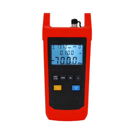
A fiber optic power meter is a type of testing instrument that measures the level of light power being transmitted through a fiber optic cable. It plays a critical role in testing and diagnosing optical networks, ensuring there are no signal strength problems and determining any difficulties. Its construction usually incorporates a photodetector with a signal processor and a display that outputs the readings in mW or dBm. Power meters are responsible for verifying the signals, thus aiding in fiber communication and system troubleshooting.
Understanding the Basics of Optic Power Meters
Optic power meters measure the optical signal’s power to guarantee its efficiency, particularly in fiber optic networks. It functions by accepting light through a photodetector that converts it to an electrical signal. This signal is then processed to tell the power level. These readings inform whether the optical signal can be sent without risking data loss or degradation in the communication system. Such ease and accuracy render optic power meters vital instruments during a network’s installation, maintenance, or troubleshooting.
How Does a Power Meter Work in Fiber Optics?
A power meter in fiber optics functions by measuring the optical power of a signal traveling through the fiber. The device operates by measuring the light signal with a calibrated photodetector which is then converted to an electrical signal. After this, it undergoes further processing to yield an accurate power measurement that is electronically displayed in dBm. Power meters are used to ensure the signal strength is within the recommended range to guarantee usefulness while reducing the chances of data loss. They are vital instruments for verifying the quality of circuits during the installation, maintenance, and even troubleshooting of fiber optic networks.
Key Features of an Optical Power Meter
- High Accuracy: Optical power meters effortlessly measure the strength of an optical signal, enabling the estimating of network performance to be highly reliable.
- Wide Measurement Range: They can measure various optical signal power levels, meaning they can be used across different types and configurations of networks.
- Multiple Wavelength Support: In addition, most devices can take measurements in different wavelengths, so they can work with many systems that use fiber optics.
- Easy Calibration: Most optical power meters have them for quick, easy, and efficient calibration, guaranteeing that they will continue accurately measuring optical power.
- User-Friendly Interface: Many devices provide inviting graphical user interfaces, enabling even novice skilled workers to operate the devices with ease.
- Portability: The optical power meter’s small, compact, and lightweight design makes it easy to use in the field for on-site troubleshooting and other portable uses.
How to Use a Power Meter for Fiber Optic Testing?
Step-by-Step Guide to Fiber Testing with a Power Meter
- Prepare the Equipment: Ensure that the optical power meter and any related items, such as fiber optic cables and connectors, are clean and in good working order.
- Power On the Device: Switch on the optical power meter and set the desired wavelength to the one corresponding to the evaluated signal: this is usually defined in the system’s specifications.
- Connect the Fiber: Connect the input port of the power meter to the fiber optic cable. Confirm that the connection is sealed and has no contamination so that precise measurements can be taken.
- Measure the Power Level: Check the reading displayed on the device. This value is the power of the optical signal and should be compared with the system’s requirements or standards to assess it.
- Document the Results: Store the values you measured for further review or analysis, identifying them so that they can be conveniently accessed later.
- Power Off and Store: At the close of testing, switch off the device and place it, together with all the accessories, in a clean, dry place to keep them in working condition.
These steps guarantee best practice measures are used in an operational environment and bring about efficient and precise measurements of fiber optic power.
Understanding Power Measurement and Calibration
Calibration helps ensure the accuracy and consistency of a device’s readings through comparison against a recognized standard. Routine calibration is needed for device aging, changes in the environment, and drift over a period of time. If calibration is not done, precision in measurement is lost, which results in the unreliability of data received. Following the manufacturer’s recommendations and using accredited instruments for calibration is essential to the accuracy of measurements and compliance with established industry regulations.
Common Mistakes in Fiber Testing
- Improper Connector Cleaning: Incomplete cleaning of fiber connectors may lead to contaminant buildup and possible false test results or even damage to the fiber. These connectors should be cleaned and inspected before any testing.
- Incorrect Use of Test Equipment: Defective test results may arise from incorrect testing device settings or lack of adherence to the manufacturer’s manual. Always confirm that equipment and connectors are appropriately set for the kind of fiber undergoing examination.
- Skipping Test Procedures: Some vital steps in testing, such as end-to-end testing or loss measurement, which are critical in getting accurate results in fiber installation, are frequently omitted.
- Poor Documentation: Failure to adequately capture test results or to appropriately file them for future reference makes working or verifying compliance impossible, leading to poor troubleshooting.
- Improper Handling of Fibers: Bending or stretching fibers too far or failing to store them correctly can degrade them over time. Always follow the appropriate handling guidelines to limit physical damage.
By avoiding the mistakes listed, one can enhance the accuracy of tests performed, minimize the time taken to troubleshoot problems and guarantee the performance of the fiber network.
Why is Calibration Important for Accurate Power Measurement?
How Often Should Power Meters Be Calibrated?
Power meters require yearly calibration to ensure accurate performance and effective use. Such timelines irrefutably meet the manufacturers’ expectations, industry standards, and typical wear and tear patterns from regular use. Nevertheless, frequent exposure to extreme environmental conditions, constant usage, or critical measurement needs might require more frequent calibration. Every device has a manufacturer’s guideline, which helps guide specific intervals. Identifying and correcting deviations from measurements is extremely important, and calibration helps ensure accurate power measurements.
The Impact of Improper Calibration on Power Measurement
Improper calibration may result in severe errors in power measurement, which can cause myopic system functioning and dependency. Calibration, or the lack thereof, whether done incorrectly, will cause measuring devices to generate inaccurate error values. For instance, even with minor drift in calibration, a ±2-3 error is bound to occur in the energy readings, which is greatly significant for precise industrial applications and monitoring power grids. Such inaccuracies can result in inefficient equipment, increase operational costs, and sometimes lead to safety issues.
Recent studies highlight the impact of improper calibration. For example, in advanced manufacturing, incorrect power measurements can halt processes that heavily depend on accurate energy input, such as laser cutting or semiconductor processing. In a similar fashion, solar inverters love improper calibration, which makes them incapable of optimal energy output and minimizes their level of compliance with grid standards. Resolving calibration mistakes guarantees compliance with regulations and operational output.
To avoid such complications, industry experts have recommended strict adherence to routine calibration checks, the use of automated calibration appliances, and meticulous measurement log book maintenance. These measures increase the chances of ensuring systems can operate within reasonable, acceptable tolerance limits, decreasing errors and helping long-term operational stability.
What are the Different Types of Power Meters Used in Fiber Optics?
Comparing Single-mode and Multimode Fiber Optic Power Meters
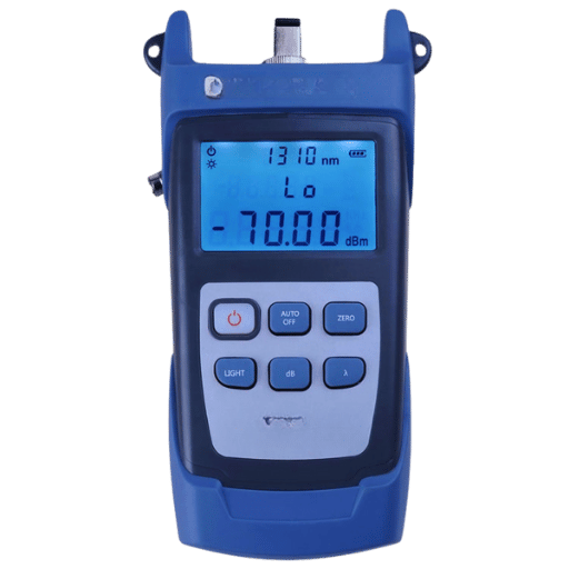
Single-mode and multimode fiber optic power meters are powerful tools that measure optical power with accuracy to help maintain network efficiency. Single-mode power meters are suited for long-haul communications utilizing narrow core fiber, usually operating at specific wavelengths of 1310 nm or 1550 nm. They are associated with high accuracy and sensitivity. The wider core, short-distance communication systems operating at 850 nm or 1300 nm utilize multimode power meters. Multimode power meters are designed to measure the higher light levels commonly found in multimode systems. The correct choice of a power meter is determined by the type of fiber as well as the performance specifications of the particular optical network under consideration.
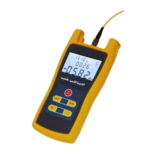
Introduction to PON Power Meters
PON power meters serve to measure both the upstream and downstream optical power levels. These devices are designed to monitor the unique PON systems, while meticulously evaluating 1310 nm, 1490 nm, and 1550 nm signal levels. PON power meters are critical while testing and maintaining fiber optic networks, as their functionality ensures precise depiction of voice, video, and data service transmission over a singular fiber. These meters can simultaneously validate system performance and assist in troubleshooting degradation cases, leading to enhanced network standard compliance.
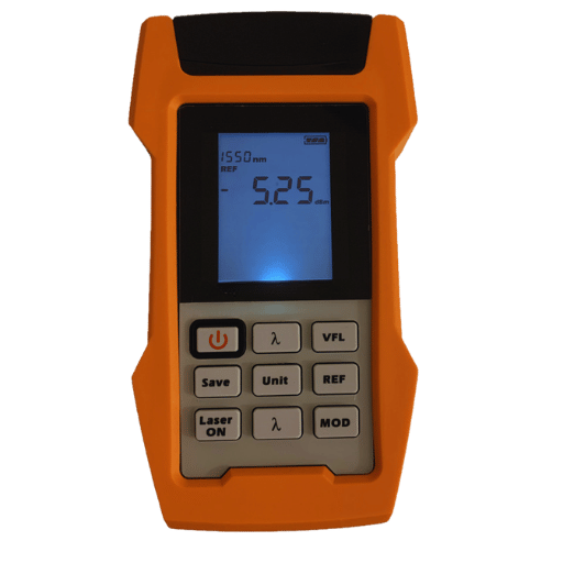
When to Use a Visual Fault Locator
A Visual Fault Locator (VFL) is a gadget that accurately identifies the exact location of breaks, bends, or faults in fiber optic cables. VFLs are mainly used for short-distance networks, connectors, and patch cords, which are not easily located using Optical Time-Domain Reflectometers (OTDRs). They use a red laser that works at wavelengths around 635 nm to 650 nm, making imperfections and damage in the fiber visible to the naked eye.
VFLs are extensively used in the installation and maintenance of fiber optic networks. For example, they are deployed during initial installs to aid technicians in ensuring correct fiber alignment by spotting discontinuities or mismatched connectors. They also assist with the fastest fault isolation in local wired data center networks and other high-density areas. In addition, VFLs help locate excessively bent fibers or microbeads that obstruct optimal signal transmission.
Because of their ease of use and cost-effectiveness, VFLs are incredibly useful for field technicians and engineers. Troubleshooting and repairs can be accomplished more efficiently with less complex signal analysis due to workers’ ability to pinpoint faults visually. Incorporating Visual Fault Locators into routine network diagnostics allows operators to improve the integrity of the optical infrastructure while greatly minimizing downtime.
How to Maintain Your Optical Power Meter for Longevity?
Best Practices for Keeping Your Power Meter in Top Condition
In order to maintain my optical power meter, I clean and calibrate it as the manufacturer prescribes. I ensure that I employ anti-lint wipes and suitable cleaning materials for the optical ports to eliminate the possibility of contamination. While not being utilized, I keep the body of the device within a protective case so it is guarded against dust, water, and breakages. I also avoid excessive handling of the power meter to avoid dealing too much force or contact with the connectors to ensure integrity over some time.
Common Repairs and Troubleshooting for Fiber Optic Power Meters
The first step in troubleshooting a fiber optic power meter is to check that the device’s power supply, battery, and/or power adapter is functioning as intended. Inspect the optical ports for dirt or damage because contamination is a frequent source of erroneous results when optical tests are conducted. If issues continue to exist, restore the device’s accuracy by recalibrating it through the manufacturer’s procedures or software tools. Optional Procedure: Replace any damaged connectors or cables with those specified by the manufacturer. If the power meter fails to operate, the manufacturer or authorized service agent must assess and repair the internal parts. Following good practices and routine maintenance can alleviate most problems.
Storage Tips for Protecting Your Test Equipment
Proper storage practices are crucial in preserving your test equipment from premature degradation while ensuring their accuracy. The equipment should be kept in a clean, dry, and moderately warm environment to avoid moisture and extreme temperature damage. When putting away the devices, use padded or protective cases to block physical impacts during storage or transportation. Keep strong sources of electromagnetic fields and vibrations at bay because they can hinder calibration or physical components. Always remove power plugs and cable adapters, and ensure all components are correctly stored to avoid losing or damaging them. Monitor environmental wear and tear alongside storage equipment regularly to troubleshoot issues as necessary.
Frequently Asked Questions (FAQs)
Q: Define a fiber optic power meter and its purpose.
A: A fiber optic or optical power meter is designed to measure optical power or the level of control of the transmitted signal within a fiber optic cable. The meter measures the output power in mW, which is essential for adequately functioning fiber optic networks.
Q: What criteria do I use to determine which fiber optic power meter suits my situation?
A: Your criteria for selecting the optical power meter (OPM) differ depending on the test applications, needed wavelengths, and types of fiber networks. Other considerations include the range of output power levels required, single-mode fiber requirements, and whether or not you test passive optical networks.
Q: Explain the functions of OTDR and contrast them with a fiber optic power meter.
A: An OTDR, or Optical Time Domain Reflectometer, tests fiber optic loss and is also used to track the nourishing fiber optic cable and other issues, including measuring the distance to the faults. On the other hand, a fiber optic power meter measures the power or loss of an optical signal in the fiber link.
Q: Why is wavelength critical when selecting a fiber optic power meter?
A: The wavelength covers the operational range of your fiber optic network. Ensure that the power meter for your network’s wavelength is selected; this helps to measure the optical power accurately.
Q: What does dbm in fiber optic power meters represent, and why is it important?
A: dBm is the unit measuring the power level in decibels relative to 1 milliwatt. Its use in fiber optic power meters is to denote the power level of an optical signal, making it possible to measure and compare differing test applications easily.
Q: Can fiber optic power meters be applied to passive optical networks?
A: Yes, a good example is the OLP-87 PON power meter, which is used to test passive optical networks. These fiber meters allow for easy measurement of power or loss in these networks.
Q: What other equipment is often combined with a fiber optic power meter?
A: A complete optical loss test set or a single optical light source is often used together with a fiber optic power meter. Such devices give a known power level that can be used to analyze an optical signal’s performance characteristics.
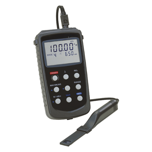
Q: What are handheld optical power meters, and when are they useful?
A: Similar to the VIAVI Optical Power Meter, handheld optical power meters are portable testers used in the field. Their convenience comes in handy when a technician needs to perform a fast and accurate test on-site, such as maintaining a fiber optic network with the help of Smartclass Fiber Mpolx.
Q: How do fiber optic power meters contribute towards maintaining fiber optic networks?
A: Fiber optic power meters help maintain the integrity and functionality of fiber networks by measuring the power of an optical signal and identifying any power loss within the fiber link. Detecting these issues helps to prevent possible impacts on network performance.
Reference Sources
1. Construction of an Automatic Embedded optic Power Meter System
- Author: Ping Fang and the others
- Publication Date: 03 June 2024
- Conference: 2024 International Conference on Optoelectronic Information and Optical Engineering (OIOE 2024)
- Summary: This work offers an embedded optic power meter system that costs less than existing devices and serves essential functions for automatic calibration. The system enhances efficiency and responsiveness with thread concurrency. It also caters to routine construction fault detection and diagnosis in communication optic fiber engineering, a known issue of nonportable optical power meters(Fang and others, 2024, pp. 131821T-131821T-6).
2. Calibration Technology Research for the Optical Power Meter
- Authors: Tianyu Liu, Xu Bai
- Published on: August 9, 2023
- Conference: 2023 IEEE 16th International Conference on Electronic Measurement & Instruments (ICEMI)
- Summary: This research is dedicated to the calibration technology for optical power meters, reviewing current technologies and suggesting a calibration system comprising a high-stability light source and an attenuator. The system can calibrate optical power meters’ nonlinear and nonlinearity corrections from -60 dBm to +10 dBm at 1310 nm and 1550 nm. The authors describe the system design and its functionality, which has proven reliable and stable in practical uses. (Liu & Bai, 2023, pp 1-7)
3. A Real-Time High Resolution and Highly Linear Wide Bandwidth MEMS Optical Power Meter
- Authors: Xuan Chen, Jiping Wu, Richard G. Baraniuk, Juhua Wu
- Date of Publication: June 1, 2022
- Journal: Sensors and Actuators A: Physical
- Summary: In this paper, the authors describe a MEMS optical power meter characterized by wide bandwidth, high resolution, and high linearity. This instrument is intended for real-time measurements, which makes its application highly beneficial in optical communications. Additionally, the authors acknowledge that measuring resolution and linearity are critical to achieving accurate measurement results (Chen et al., 2022).
Post Views: 6,462


