For effective operation and upkeep of a network, the world of fiber optics demands attention to detail and dependability. One of the most important components of a fiber optic cable is the OTDR which stands for Optical Time Domain Reflectometer. With the help of this device, engineers and technicians can accurately assess and diagnose fibers and cables. This guide seeks to clarify the perceived complexities of OTDR testing by studying its core concepts, usages, and what it reveals concerning the state of a fiber optic network. For industry veterans and novices alike, this article facilitates understanding of the functions of an OTDR, its critical role in fiber optic testing, and how to analyze the results it produces for the best possible maintenance and longevity of fiber installations.
How Does an OTDR Work?
Light Pulse Reflection: Key to OTDR Functionality
To operate an OTDR, a series of light pulses are injected into a fiber optic cable. The pulse travels down the fiber, and light is captured as it comes back while being reflected. Each of these reflections takes place at different locations depending on the radiuses’ of curvature or changes in the fiber with respect to connectors, splices, or other imperfections. The OTDR captures and analyzes the reflections created by these varying changes. So, by assessing the time of flight of the light reflects as well as how intense the light is, the OTDR can determine the characteristics or features of the event with high accuracy. This helps the technician estimate anticipated problems, evaluate the quality of fiber, and verify the standards of installations.
Understanding Backscattered Light in OTDR
Backscattering is a critical part of OTDR functionalities since it helps analyze properties of the optical fibers. When light pulse is launched, because of backscattering, some fraction of the light will scatter and travel towards the OTDR. The OTDR can get information regarding the slow rate of scattered light, therefore the OTDR can provide how much the fiber is being attenuated, the presence of faults and identify where those faults exist along the cable. These precise measurements are very vital to aid reliability of fiber optic communication systems.
The Function of OTDR Trace on fiber optics analysis
An OTDR trace refers to a graphical representation of the operational characteristics of the optic fiber; distance along the fiber is plotted versus the power of the backscattered signal. This trace holds importance in the evaluation of fiber optic cables because it indicates splice losses, amount of connector losses, and reflections attributed to bends and breaks in the fiber. The peaks in the trace often mark where these events occurred, and the diiferential loss in the signal level indicates the attenuation of the fiber.
Most advanced OTDR equipment includes automation features for event identification and event analysis. Such features allow them to locate and measure anomalies precisely. For instance, the loss in the single mode fibers is generally accepted to be 0.35 dB/km at 1310 nm and 0.22 dB/km at 1550 nm. By measuring the detected attenuation with these values, deviations from the norm which indicate the necessity for repair or substitution can be identified.
Moreover, OTDR traces can quantify the length of the fiber and assist in gauging the attenuation coefficient, insertion loss, and return loss. The ability to analyze such data ensures that system parameters are met and the network is functioning optimally. The growing sophistication of OTDRs, such as those with high sampling resolution or enhanced dynamic range, empowers many professionals to examine long-haul networks and diagnose problems with precision in both short and long fiber runs.
What Makes Fiber Loss a Major Consideration for OTDR Testing?
How Fiber Attenuation Influences Results from an OTDR
OTDR results are impacted by fiber attenuation because, as the light signal travels along the fiber, its strength is diminished. This loss can impede the OTDR’s ability to detect and analyze events like splices, bends, or breaks, particularly over long distances. Increased fiber attenuation and loss of the dynamic range of the OTDR can significantly lower the accuracy with which faults are detected and located. An appropriate allowance for fiber attenuation, particularly at the splice loss, will improve the performance of the OTDR and hence ensure reliable measurements and diagnoses in fiber optic networks.
Techniques of Determining Fiber Loss
- An optical time domain reflectometer (OTDR): this technique utilizes pulse of light to measure the loss along a fiber optic link. It detects such events as bends and splices or breaks and Draws a Graph which displays loss in proportion to distance into the fiber.
- Optical Power Meter and Light Source: This technique involves injecting and optical signal into the fiber. An optical power meter is used to estimate the signal at the other end of the fiber to ensure that light can traverse the fiber effectively. The difference between the input and output power provides the total optical loss in the fiber link.
- Testing for loss of Insertion: This technique quantifies the loss from specific elements like connectors or splices by examining the differences in optical power before and after the element in question.
All methods are equally precise and trustworthy; however, the selection must be made in regard to the particular application and the equipment at hand.
When Should You Consider Employing an OTDR for Troubleshooting?
Determining Defects Within a Fiber Network
The OTDR is considered the most effective tool for fiber network troubleshooting. It detects breaks, bends, and splice losses along the fiber. An OTDR sends light pulses through the fiber and computes the reflected signals to locate the problem area. With such feature, OTDR greatly assists in maintaining the network by ensuring that its performance will be optimized and downtime will be minimized. Use an OTDR for troubleshooting when exact fault detection and localization is required.
Verification and Testing of Fiber Optic Systems
- Performing Visual Inspection. In the first stage, carefully inspect fiber, connectors, and cables to search for damage, dirt, and improper connections as well.
- Test Signal Continuity. Through the utilization of a Visual Fault Locator (VFL) as well as light source and power meter, check for signal continuity and confirm there is no break in signal offered through the fiber.
- Determine Power Levels. An optical power meter should be employed to confirm the signal’s power level meets the specified requirements.
- With OTDR Accuracy Incremented Localization Of Lateral Connections. The dysfunctional parts such as breaks, bends, and/or undue excess of splice losses along the fiber lens are diagnosed and their mark location is established on the fiber diagnosed.
- Document Results. All outcomes from the test, including power readings and fault location data, must be recorded in order to facilitate future analysis or remedial planning.
Which Types of OTDRs are On the Market?
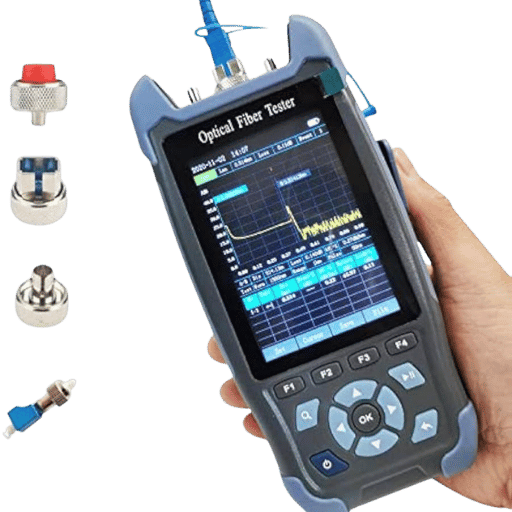
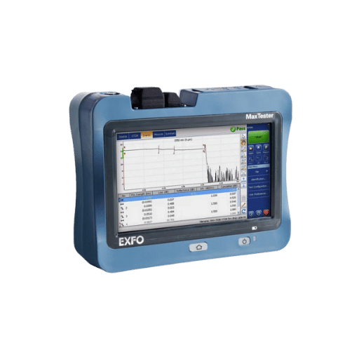
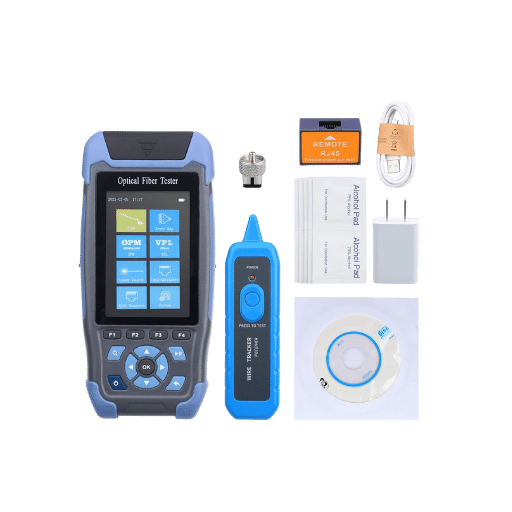
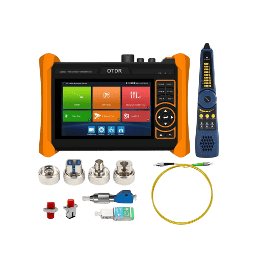
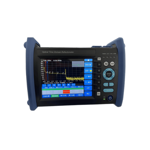
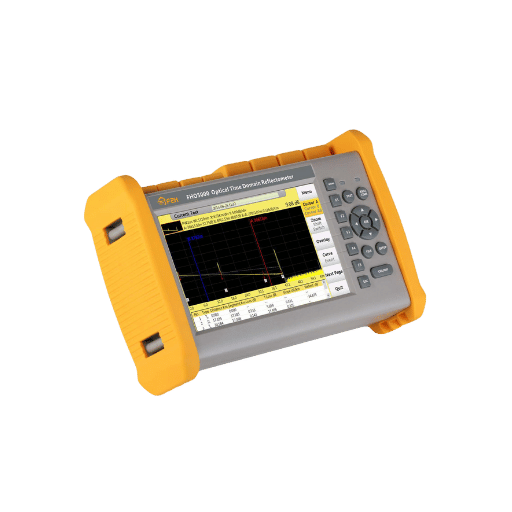
Bench-Top OTDRs Versus Hand-held OTDRs
Portable OTDRs are small field devices that can be used in any location. Their compact size, battery power, and light weight makes them essential tools for helping field technicians conduct regular checks and problem solving within an area or region. Bench-top OTDRs are larger, non-portable units that tend to be more advanced, offering high accuracy and sophisticated processing power. These models work best in laboratory settings or controlled chambers where precise analysis in detail measurements of two fibers is needed. The preference of selection is based on the specific circumstance – with portable units focusing on mobility and convenience, while bench models are more task-focused and offer higher accuracy.
Differences Between Multimode and Single-Mode OTDRs
Choosing between single-mode and multimode OTDRs comes down to the optical fiber and application’s purpose. Single-mode OTDRs are suitable for single-mode fibers that are frequently utilized in long-range telecommunication and high speed data network because they have low signal loss and can transmit over long distances. They typically operate using three wavelengths- 1310 nm, 1550 nm and sometimes 1625 nm. These OTDRs offer high accuracy along with long testing ranges which makes them best suited for metro, long-haul, and enterprise networks.
Conversely, multimode OTDRs are designed for multimode fibers which are commonly used in local area networks (LANs), data centers, and building interconnections that are comparatively high bandwidth and short distance. These OTDRs typically operate at 850 nm and 1300 nm, identifying fiber networks with shorter testing ranges, but better capturing multimode performance issues.
While single-mode and multimode OTDRs can be operated by the same user, it is imperative to know that they are not interchangeable, as there are significant differences between the two. For the case of these devices, the latest modern OTDRs have transformed the devices by increasing the dynamic range, trace analysis software, and event detection automation. This ensures that default devices mode single or multi meet sophisticated network coverage requirements. What is vital while these devices may appear the same and more advanced is understanding if project specifications like fiber type, operational wavelength, distance requirements, and budget limit are precisely defined. This guarantees the selected OTDR has optimal testing efficacy and dependability.
An OTDR Test workflow: Procedure and protocols
Your Fiber Optic cables can be prepared as follows to perform an OTDR test:
- Step 1: Inspection and Cleaning of Fiber Connectors- Ensure that all connectors are free from dirt, dust, or debris. Clean emblems using fiber scrub tools such as a lint-free wipe and isopropyl alcohol, or dedicated fiber cleaning kit capable of minimizing contamination.
- Step 2: Confirm Cable and Device Connector Compatibility- Verify that the fiber’s connectors are compatible with the ports on the test equipment. Use appropriate plugs if needed and verify all devices are able to connect using their respective ports.
- Step 3: Secure, Avoid Bends and Tension on the Fiber Optic Cable- Make sure no bends or tension is applied to the cable to avoid damage or incorrect testing results. Make sure the cable is laid out in the right format so that it does not get damaged or give inaccurate results.
- Step 4: Confirm Proper Fiber Termination- Ensure both ends of the fiber are terminated and connected to the sockets meant for testing.
To analyze an OTDR test, consider the following:
The test results from the OTDR device essays stamp on vital issues regarding the status of a fiber optic link. Some of the key points to consider include all the fiber length, overall distance the OTDR can reach. This aids in crosschecking if the fitted cable corresponds to the design values.
Event Markers – The OTDR trace will show reflection or loss points such as splices, connectors, or faults. Damaging or astonishingly bad installations will usually indicate high loss points with some event.
Insertion Loss – Refers to the power loss on the events. Low values of insertion loss are associated with good and vice versa is true with higher values.
Return Loss/Reflectance – Determines how much light is reflected to the source. Increased reflectance observed will adversely affect the transmission performance especially the loss on the splice.
The OTDR trace interpretation is critical in determining the existing problems and validating operational performance of the fiber optic system. Remember to always check the designs with your results against set criteria or industry standards for a thorough evaluation.
Impacts of Connector and Splice Quality on Fiber Links
Both the connectors and splices quality influences the overall performance of a fiber optic link. Splices that are done poorly and low quality connectors lead to higher insertion loss and reflectance, thereby reducing the signal strength and transmission quality. Losses can be minimized and optimum performance maximized with proper alignment and cleanliness during installation. The use of high-quality materials and compliance to the established best practices greatly improves network stability and signal continuity in the long run. Connectors and splices should always be visually inspected and tested to confirm compliance with defined requirements.
How Do You Interpret an OTDR Trace?
Recognizing Events on an OTDR Trace
In order to interpret an OTDR trace, the most important step is recognition of the vital steps like the initial or launch points, connections, fiber splices and the fiber end. Each event that occurs is depicted by a change in the trace of a peak, dip, or even sudden loss which may suggest two events happened at the same time.
- Launch Point– The initial spike in the trace indicates the fiber the OTDR is connected to.
- Connectors and Splices– Minor peaks and dips on the trace can represent connectors or slit points; losses here must be in alignment with the expected values.
- Bends or Faults– A sharp drop in the trace corresponds to fibers that have bends, breaks or even defects.
- Fiber End– Fiber ends are represented on the future as a steep drop usually accompanied by some reflective noise.
With this, use these features as well as the OTDR’s event table data to prepare an analysis and determine the events parameters and characteristics for compliance with given standards.
Concepts of Reflectance and Dead Zones
Reflectance is the ratio of light being reflected back towards the OTDR from a selected point in the fiber, like a connector or a splice. A highly reflecting segment suggests poor performance because of a faulty connector or mismatched parts. Dead zones comprise regions of the OTDR trace where some events cannot be recognized with clarity. These are caused by strong signals reflecting too much energy or the pulse width set too low. To reduce dead zones, select an appropriate pulse width and add a launch fiber to better define events close to the beginning of the fiber. Proper understanding of reflectance and dead zones is importantin observing the integrity of the fiber optic system.
Frequently Asked Questions (FAQ)
Q: An OTDR: What is it and How does it function?
A: An OTDR, also known as Optical Time Domain Reflectometer, is an advanced testing device used to troubleshoot problems within a fiber optic cable infrastructure. It functions by generating a light pulse within the fiber, then assessing the quantity of backscatter and reflection which is emitted. Because of this, the OTDR is able to examine the condition of your fiber, finding faults like breaks, bends, and even loss of signals. The probe placed on the fiber, known as OTDR, emits a pulse which is absorbed and then regurgitated by refracting light within the undamaged fiber. The sensor records the time and amount of refracted light, revealing the fibers properties.
Q: What is link loss and the relevant measurement through OTDR verification?
A: Link loss is a representation of line connectivity, stemming from the loss of signals in the fiber optic link and is often represented in decibels (dB). An OTDR verifies link loss by measuring the backscatter and light reflection while it propagates through the fiber. The OTDR measures the link’s insertion loss by evaluating the power levels at various sections along the fiber, thus providing comprehensive detection of the fiber cable’s functionality and presence of damages that could disturb the flow of signals.
Q: In what ways does the OTDR differ from other methods of testing fiber?
A: The OTDR is referred to as a Tier 2 testing method. The levels of detail provided during analysis of the tests are more advanced than what is offered in a simpler Tier 1 test. Unlike power source and light meter tests which just assess loss from one end to the other, an OTDR is capable of locating losses somewhere within the fiber cable itself. Additionally, it will determine the loss within dilapidated portions of the cable. These include splices, connectors, and bends. It is for these reasons that troubleshooting existing fiber installations and verifying the quality of new fiber deployments is quite easy with OTDR testing.
Q: Give examples of faults that an OTDR would be able to pinpoint in a fiber cable.
A: An OTDR is capable of locating a variety of faults in a fiber cable which includes: 1. Breaks and cuts within the fiber 2. Overbending which may result in signal loss 3. Reflective or high loss splices 4. Reflection by dirty fiber end faces 5. Broken or defective connectors 6. Water in the cable 7. Dead zones of attenuation 8. Gradual deterioration of the fiber due to aging This is done so the technicians will know what steps to take to sustain or fix the fiber optic network.
Q: Explain why fiber certification is important and discuss the role of an OTDR in the process.
A: Certification is important to verify that a fiber optic installation was done properly and that it functions as it should. An OTDR assists in fiber certification in the way it captures the fiber documents’ details. It keeps track of values like the fiber length, attenuation, and loss at the connectors and splices to make sure that the light is transmitting through the fiber as it should. The data is then used to create certification reports which are needed to check that the too cable plant meets the relevant regulations and requirements. Using an OTDR to certify the cabling helps avoid problems later on and it guarantees the health of the fiber network for a longer time.
Q: What are some best practices for fiber testing with an OTDR?
A: Here are a few best practices for OTDR use: 1. Always utilize suitable launch and receive fibers. 2. Pick the right wavelength corresponding to the fiber being tested. 3. Adjust the pulse width to suit the fiber length and required resolution. 4. Remember to clean the OTDR side and the far end of the fiber’s connections. 5. For precise measurements of splice loss, test the fiber in both directions. 6. Use the right refractive index for the fiber under test. 7. Analyze the OTDR trace with the right level of skepticism and distinguish real problems from artifacts. 8. Consistently mark and service the OTDR as required to avoid discrepancies in output. Adherence to these will ensure correct and credible OTDR test results, particularly for the first connector.
Q: What is unique about an OTDR such as Fluke Networks OptiFiber when compared to other test equipment?
A: Advanced OTDRs, such as the Fluke Networks OptiFiber, have several benefits compared to basic test equipment: 1. They usually offer a straightforward interface with automated test options. 2. These devices are capable of accurately measurimg short fiber links. 3. Several devices provide easy documentation through built-in reporting and cloud integration. 4. Some devices provide advanced features such as macrobend and PON testing. 5. A few models offer visual fault locators with fiber inspection scopes. 6. Test equipment developed for longer and more complicated networks have higher resolution and dynamic range Unlike basic OTDRs, these features advanced OTDRs increase functionality and productivity when performing professional fiber optic testing and troubleshooting.
Reference Sources
1. Event Recognition Method Based on Dual-Augmentation for a Φ-OTDR System with a few training samples utilizing light from the OTDR test.
- Authors: Yi Shi et al.
- Journal: Optics Express
- Publication Date: August 4, 2022
- Key Findings:
- In this paper, event recognition for the Φ-OTDR system is executed with few-shot techniques, concentrating on the first connector. Time series transfer and CycleGAN are employed for dataset augmentation, as the training dataset is improved with light from the OTDR test.
- The solution in question works with real responses in real-time scenarios and demonstrates its usefulness by attaining a high (90.84%) accuracy count with restricted training samples.
- Methodology:
- The authors gathered information with the aid of perimeter security scenarios and applied YOLO-based model for feature recognition. The method seeks to enhance the recognition of intrusion events on OTDR systems.
Citation: (Liu et al., 2022, pp. 10096–10109)
2. High-Performance Distributed Dynamic Strain Sensing by Synthesizing Φ-OTDR and BOTDR
- Authors: Haoting Wu et al.
- Journal: Optics Express
- Publication Date: March 9, 2023
- Key Findings:
- This investigation suggests a new method of integrating Φ-OTDR and BOTDR for distributed dynamic strain sensing while maintaining high sensitivity and precision in vibration detection of two events.
- The technique is applicable for numerous domains, such as monitoring the health of structures, and helps in the tracking of data in real-time.
- Methodology:
- The authors carried out a number of practical tests to assess how well the proposed system could function in real world scenarios, in this case, the detection of low frequency vibrations.
Citation: (Wu et al., 2023, pp. 18098–18108)
3. Pilot-Scale Testing of Natural Gas Pipeline Monitoring Based on Phase-OTDR and Enhanced Scatter Optical Fiber Cable
- Authors: Nageswara Lalam et al.
- Journal: Scientific Reports
- Publication Date: August 28, 2023
- Key Findings:
- The authors carried out a number of practical tests to assess how well the proposed system could function in real world scenarios, in this case, the detection of low frequency vibrations.
- The study highlights the need to employ regularized scatter optical fiber cables for better monitoring operability.
- Methodology:
- The authors performed the preliminary experiments to assess how well the Φ-OTDR system performs in practical situations while attempting to analyze its performance of disturbance detection in the pipeline.
Citation: (Lalam et al., 2023)
4. Optical fiber
5. Decibel
Post Views: 8,067


