As AI, cloud computing, high-performance computing (HPC) and explosive data growth drive ever-higher traffic, an increasing number of data centers are migrating from 100G to 400G. Compared with rebuilding a network from scratch, smoothly evolving an existing 100G fabric to 400G is more cost-effective and can deliver a 4× increase in bandwidth in a short time. Rather than deploying an entirely new architecture, migrating the current 100G network to 400G significantly improves throughput and network efficiency, reduces upgrade costs and downtime, and better supports future expansion to 800G and 1.6T.
In this process, 400G optical modules, QSFP-DD/OSFP form factors, single-mode vs. multimode cabling, and the typical 4×100G breakout architecture are the key technical elements. Whether you are scaling a spine-leaf topology, horizontally expanding an AI cluster, or upgrading a large enterprise campus network, planning a clear, reliable “100G → 400G upgrade path” has become a core task for data-center operations teams.
This article walks through the upgrade process step-by-step — from link planning, hardware selection and cabling design to compatibility checks and cost control.
Pre-Upgrade Checklist: Is Your Network Ready for 400G?
Before planning the migration from 100G to 400G, the most important step is to thoroughly assess your existing network. This evaluation determines which upgrade path you should take, which components need to be replaced, and what the overall budget will look like. Below are the key items you must confirm before officially starting your 400G upgrade.
Does your switch support 400G?
The switch is the core of the entire upgrade. If your current switches cannot support 400G, both the complexity and the cost of the migration will increase significantly. Therefore, make sure to verify:
1.Whether the switch has QSFP-DD or OSFP ports
These are the mainstream form factors for today’s 400G optics.
QSFP-DD: Highly compatible with existing QSFP families; ideal for clusters and enterprise data centers.
OSFP: Offers stronger thermal performance; commonly used in AI/HPC large-scale clusters.
2. Whether the switch supports the 400GbE (IEEE 802.3bs) standard
This determines whether the ports can correctly recognize 400G PAM4 modulation, perform traffic management, and handle link-layer configuration.
3. Whether a line card or firmware upgrade is required
Some switches may have the correct physical interfaces but still require:
Updating the system software
Upgrading the license
Replacing line cards that support higher bandwidth
Does Your Existing Fiber Meet 400G Cabling Requirements?
400G imposes significantly stricter requirements on fiber type and quality than 100G, especially under multi-lane PAM4 signaling.
1.Multimode Fiber (MMF) — Suitable for short-reach applications
If the cabling fails any of these criteria, 400G transceivers will frequently suffer from high bit-error rates (BER), random link flaps, or complete failure to establish a stable connection.
Is Your Data Center Layout, Cooling, and Cable Management Ready for 400G?
400G networks consume significantly more power than 100G, and the increased number and thickness of cables introduce new deployment challenges. Before upgrading, evaluate the following:
1.Does the cabinet have enough physical space to accommodate higher-density 400G ports?
2. Is the airflow direction (front-to-rear or front-to-front) aligned with the orientation of the optical transceivers?
3. Will the cabinets require optimized air ducts or replacement with higher-CFM fans?
4. Can existing cable management trays and routing accommodate thicker MPO trunks and a dramatically higher fiber count?
For high-density 400G OSFP systems, insufficient cooling can trigger automatic module throttling or link drops. Proactive planning of cooling and cable routing is essential to avoid performance degradation or outages.
Three Mainstream Upgrade Paths from 100G to 400G
Data centers of different sizes can choose the migration approach that best fits their needs.
Option A: Breakout 400G into 4×100G (Most Common Approach)
Ideal for:
Scenarios where upper-layer switches are upgraded to 400G while servers remain on 100G
Teams that prefer phased migration to reduce upfront investment
It offers the lowest cost, is easy to deploy, and seamlessly fits into existing 100G architectures.
Option B: End-to-End Upgrade to 400G (Best for Core Networks)
Ideal for:
Full Spine/Leaf upgrades
AI, HPC, and cloud platforms requiring large-scale horizontal expansion
Common module selections:
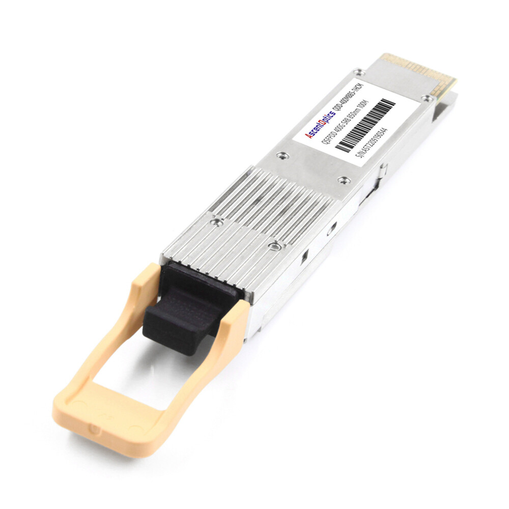
Short-reach: 400G SR8 / SR4.2
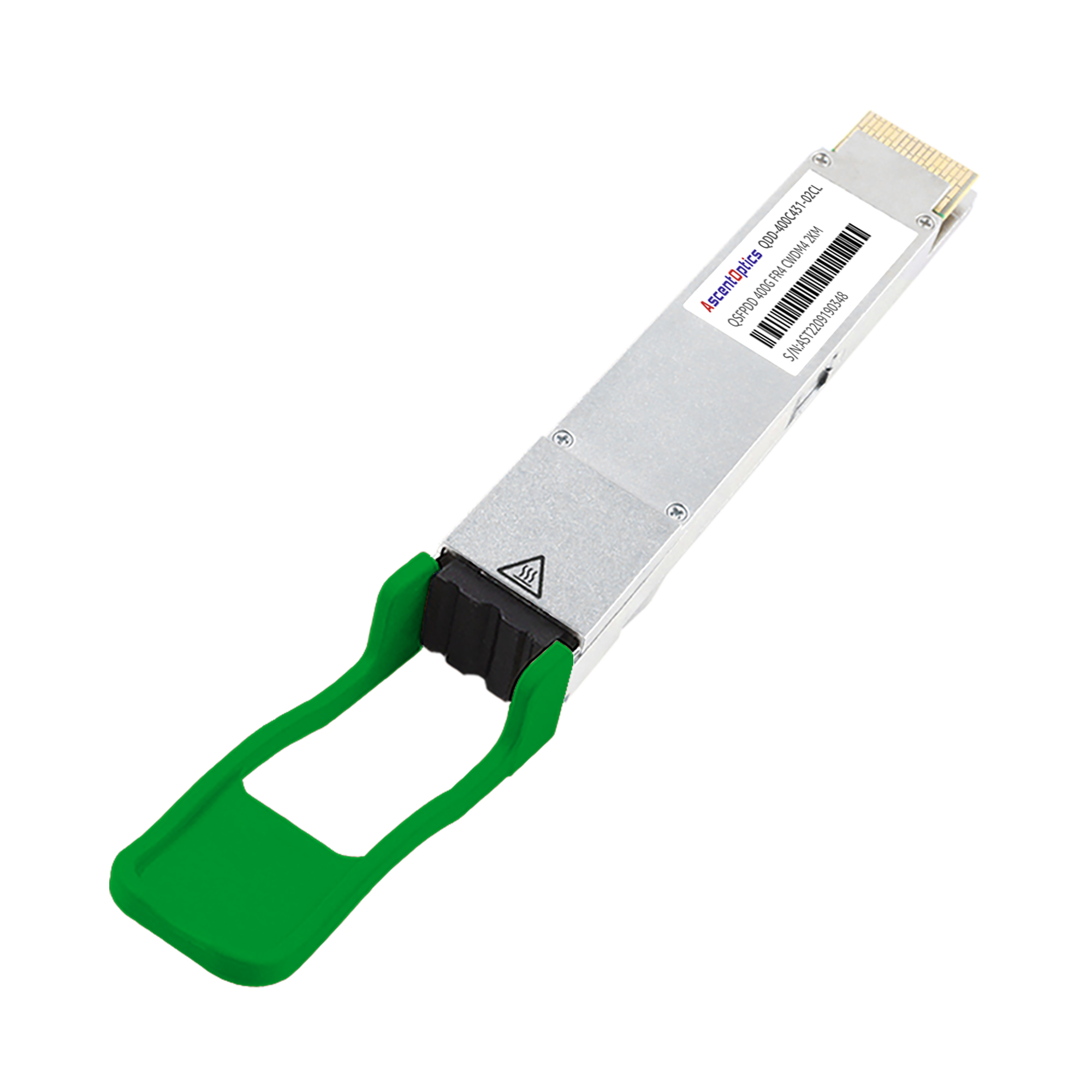
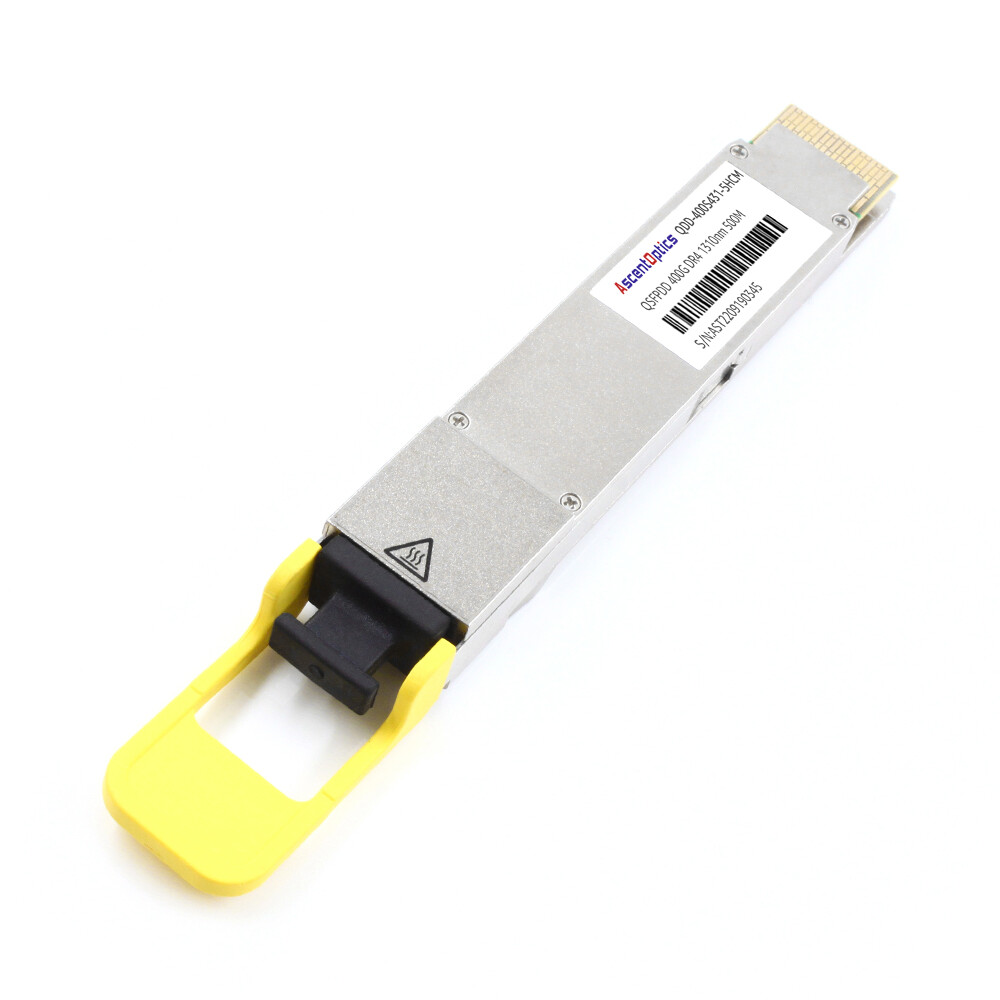
Medium-reach: 400G DR4 (500 m), FR4 (2 km)
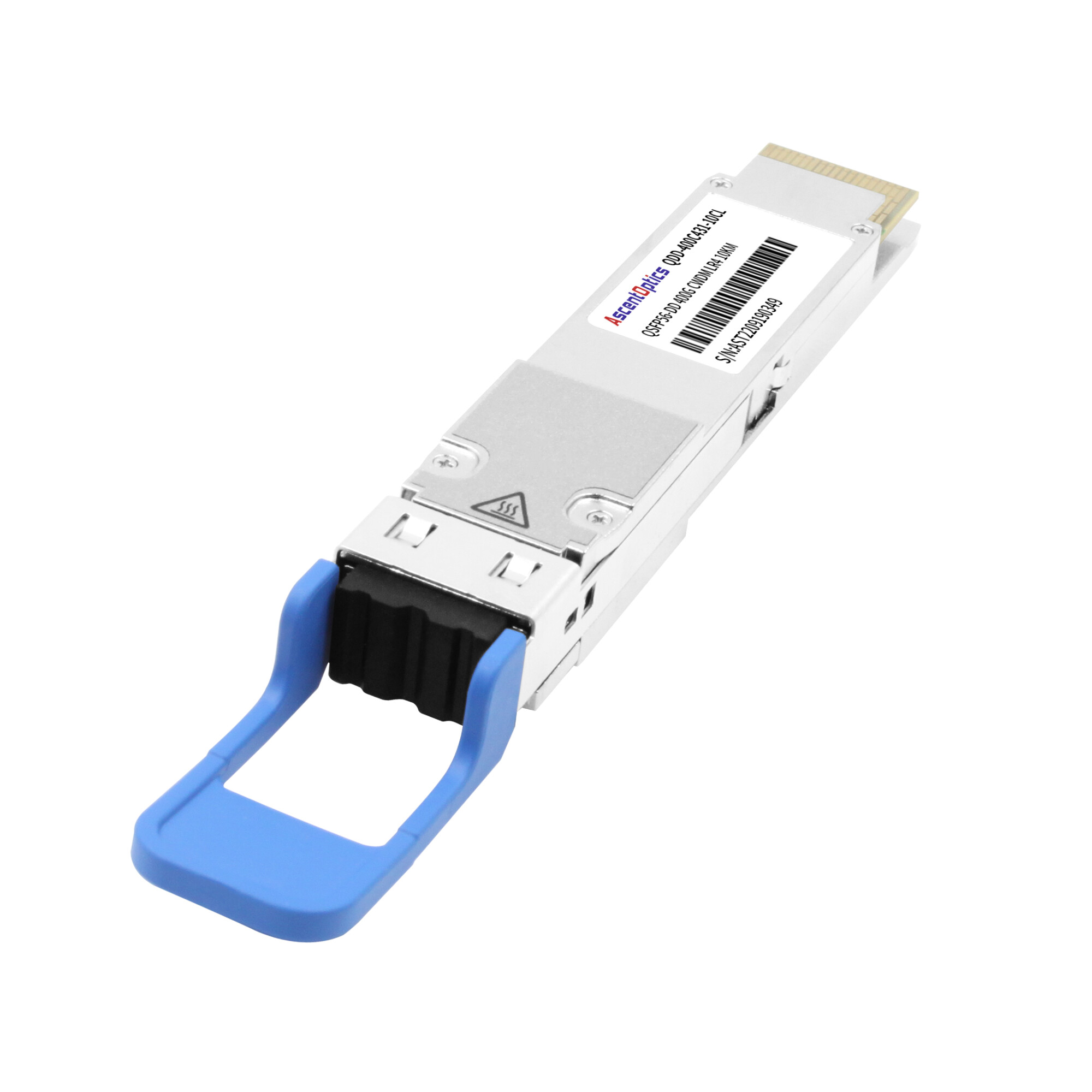
Long-reach: 400G LR4 (10 km)
Data Center Interconnect (DCI): 400G ZR / ZR+ (40–120 km)
Advantages:
High performance, low latency, maximum bandwidth utilization, and better alignment with future upgrades to 800G / 1.6T.
Option C: Transitional Path: 100G → 200G → 400G
Ideal for:
Node equipment does not yet support native 400G ports
Limited budget with phased, incremental expansion
Common in HPC clusters that prefer step-by-step upgrades
Cabling Recommendations
In 400G networks, cabling infrastructure is the most frequently overlooked yet most problematic component. High-density, multi-lane PAM4 transmission imposes far stricter requirements on fiber quality, end-face cleanliness, and connector standards than 100G ever did. Proper cabling planning not only maximizes link reliability but also dramatically reduces future upgrade costs.
Multimode Fiber (MMF) Cabling Key Points
Multimode fiber is suitable for short-reach scenarios (intra-rack and inter-rack), but it is extremely sensitive to end-face contamination.
1.400G SR8 → Must use MPO/MTP-16
SR8 employs 8×50G PAM4 lanes and requires a full 16-fiber interface.
Any dirt on the end-face or connector mismatch will cause high bit-error rates (BER) or link flapping.
2. 400G SR4.2 (BiDi) → Uses MPO-12
SR4.2 leverages dual-wavelength multiplexing to reduce cabling complexity while still maintaining strict insertion-loss requirements.
Single-mode Fiber (SMF) Cabling Key Points
Single-mode fiber has become the “default choice” for 400G, especially for inter-rack, backbone networks, and future-proof deployments.
Ideal for reaches up to 500 m, most commonly used between cabinets or across floors.
2. 400G FR4 / LR4 → Standard duplex LC connectors
Uses 4-wavelength multiplexing (CWDM4), eliminating the need for multi-fiber trunks and greatly simplifying cabling.
FR4 (2 km) and LR4 (10 km) are the most popular options in data centers.
SMF is the best choice for future expansion to 800G / 1.6T
Upcoming 800G and 1.6T generations (e.g., 800G DR4, FR4, etc.) will continue to rely primarily on single-mode optics. Deploying SMF today therefore maximizes investment protection and enables the smoothest possible migration path in the years ahead.
Cost-Control Tips: Upgrading to 400G Can Be Surprisingly Affordable
With smart planning, 400G doesn’t have to be expensive.
1.400G FR4: The most cost-effective mainstream choice
2 km reach
Uses standard duplex LC connectors → simplest cabling
Mature, stable, and widely applicable
Lower unit price than SR8 or DR4
Ideal backbone solution for the vast majority of data centers
400G QSFP-DD FR4
2. Breakout (1×400G → 4×100G) saves more money than end-to-end 400G
Extends the life of existing 100G equipment
Reduces large upfront hardware spend
Offers maximum flexibility when upgrading spine/leaf layers
3. Third-party compatible transceivers cut costs by 50–70%
Third-party modules (e.g., FS, AscentOptics, Innolight, Vitex, etc.) now match OEM performance and compatibility while delivering better overall value:
Faster lead times
Flexible coding for any switch brand
Dramatically lower price
Proven at scale in hyperscale and enterprise environments
4. Deploy single-mode fiber once — future-proof forever
A one-time investment in SMF infrastructure will seamlessly support:
400G today
800G tomorrow
1.6T the day after
→ Eliminates the massive re-cabling costs that come with future upgrades.
Do these four things right, and your 400G migration can easily cost less per gigabit than staying on 100G ever did.
Upgrading from 100G to 400G is a key step toward a high-bandwidth data center. With proper planning of switches, transceivers, and cabling, the transition can be completed smoothly without excessive cost, while preparing the network for future 800G/1.6T expansion. Start with a thorough assessment and upgrade step by step to build a more efficient and scalable infrastructure.