In contemporary telecommunications, fiber optic splicing is quintessential because it allows effortless connection and integration of data across a network. Whether setting up a new high-speed internet pipeline or restoring service on a current system, knowing the methods of fiber optic splicing is vital in reducing downtime and increasing productivity. This article covers two of the basic methods of splicing fiber optic cables– fusion and mechanical – and discusses the tailor-made tools that make exacting connections possible. In conclusion, readers will learn the importance of these methods of fiber optic networks and their importance to industry experts.
What is Fiber Optic Splicing?

The process of connecting two optical fibers in a manner that allows light to move through them continuously is known as fiber optic splicing. This is usually done to repair broken fiber cables or to add length to a fiber cable during network installations. There are two primary methods of splicing: fusion splicing, which involves melting the glass ends together with heat, and mechanical splicing which involves precise alignments of the fibers for each other and fixing their position with a mechanical device. Through either process, as minimal signal loss as possible is aimed to ensure maximum reliability in communication systems for optics.
Introduction to Fiber Optic Technology
Thanks to their unparalleled effectiveness, dependability, and versatility, telecommunications, and data transfer have been revolutionized by fiber optics technology. With light being the transmission medium, fiber optic cables transfer data at a significantly faster rate than copper cables. Recent reports indicate that the global fiber optic market is estimated to increase from 8.5 billion to 12.9 billion by the year 2028. This advancement is due to the rising requirements for high-speed internet, the development of 5G networks, and improvements in smart technologies.
The newer optic fibers’ ability to carry signals beyond 1 TB per second makes them very important in the construction of emerging technologies such as IoT networks, cloud computing, and AI servicing, in addition to making them less prone to signal degradation. In addition, the composition of fiber optics using thin glass or plastic fibers makes them suitable for dense urban and industrial environments since they are low in electromagnetic interference.
Today, fiber optics are vital to global infrastructure, which includes communication networks between continents via submarine cables. These cables are projected to carry more than a million kilometers of fiber optic cables by 2024, carrying 99% of digital information, transactions, streams, and interactions that take place daily across the globe, estimated to be in the billions. The dependency on global connectivity reaffirms the investment in sustaining the digital economy through fiber optics.
Further investment in research and development is anticipated to innovate ultra-secured data transfer methods, quantum communication, and ultra-fast data processing, making fiber optic technology more sophisticated and flexible than it already is. These expectations emphasize the use of fiber optics as the primary component of communication infrastructure today and in the future.
Why Fiber Optic Splicing is Essential
Fiber optic splicing is key in establishing continuous optical paths on a network while keeping signal loss to a minimum. It allows for easy repair and extension of existing fiber optic cables which facilitates data transmission. Splicing is also vital in network updates or upgrades in order to install new parts of the network with minimal disruption to the existing structure. Fiber optic splicing helps to strengthen the connection points and mitigate signal attenuation which facilitates the economical and dependable functioning of advanced telecommunications systems.
Differences Between Fusion and Mechanical Splice
First and foremost, let’s clarify that regardless of the types of fiber optic splitters in focus, whether both fusion splicing and mechanical splicing are considered, they bear distinct and ownable features. Fusion Splicing First comes fusion splicing which is defined by heat and a permanent welder.
With the two fiber ends being spliced, they form a strong and low-loss connection epitomized by welding. This means it has excellent optical performace while getting minimum signal loss fusion splicing is perfect for high-precision joints even when used and a great period. The coupled joints are, however, specially crafted joints as this technique requires trained physiotherapists and specialized equipment.
Mechanical Splicing While in mechanical splicing, fiber ends within a sleeve or housing are not permanently bonded. It is widely accepted that it is quicker and easier to perform when splicing fiber, as it is less demanding of equipment, and in most practical scenarios, less limb-equipped splicing is so much easier Fusion splicing too comes with moderate performance, however with adequate resources. It also performs best when installation is low-budget and temporary. This technique however will always out more inserted loss than broken microwave shutters.
For primary and most practical applications these techniques provide numerous options for implementation; this shifts focus toward cost performance for effective budget planning.
How is a Fusion Splice Performed?
Tools Required for Fusion Splicing
Like any other process in welding, fusion splicing requires a delicate approach and specialized machinery for the best results. These below named tools are quintessential and I have provided their descriptions.
Fusion Splicer
A fiber optic fuser is the most important component as a Determine the core equipment piece. It opens junctions within fibers, aligns them, and sticks them together utilizing an electric arc. As splicer technology is changing, modern fusion splicers employ sophisticated alignment systems and loss estimators that calculate the attenuation of optical signals to improve the spicing loss accuracy such that for single-mode fibers, the insertion losses could be made lower than 0.02dB.
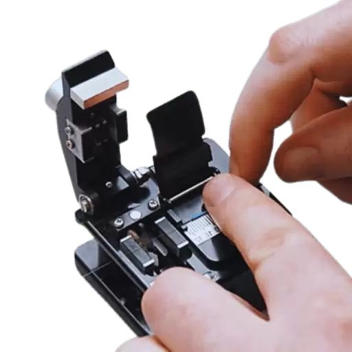
Fiber Cleaver
A cleaver is critical for producing clean and precise cuts on the fiber ends before slicing. High-precision cleavers have demonstrated success in achieving cleave angles of under half a degree, consequently, resulting in lower splice loss.
Fiber Strippers
These tools are used to remove the protective coating from the optical fibers exposing the glass core underlying it. While there are various types of strippers, thermal strippers, which utilize heat at a controlled temperature, are common due to their clean and even results.
Cleaning Tools
To splice fibers together, the ends have to be prepped and cleaned and for this purpose, a variety of tools are used. To get rid of dust, oil, and debris that can interfere with the splice, lint-free wipes along with isopropyl alcohol and pressured air are used.
Oven for Heat Shrink Application or Splice Shield
Once the splice has been done, a splice protector or heat shrink sleeve is utilized to cover and constructively reinforce the connection. Certain fusion splicers come with built-in heat ovens for ease of use.
Visual Fault Locator
The VFL is used to inject a beam of visible red light into the fiber to assess the integrity of the splice. Problems with the splice such as cracks or offsets of the fiber ends will result in scattering of the light enabling quick recognition of problems.
Workstation and Fiber Holders
During the splicing, a stable workstation and fiber holders make sure that the fibers are properly held in place. Certain holders are specific to certain splicer models or ribbon fibers.
The combination of all these tools offers efficiency, accuracy, and reliability during a fusion splicing process. This guarantees limitations to insertion loss and maximizes the mechanical strength of the splice junction. The knowledge of how to effectively operate the tools and their proper upkeep is what creates consistent high-quality results.
Step-by-Step Fusion Splicing Process
Prepare the Fiber
Using a fiber stripper, peel off the protective coating from either end of the fiber ensuring that the bare glass is exposed. Clean the visible fibers with isopropyl alcohol to remove any dirt or debris.
Cleave the Fiber
Use a precision fiber cleaver to trim the fiber ends so that they are perpendicular to the length of the fiber at 90 degrees. Properly cleaving is paramount for efficient splice loss mitigation.
Align the Fibers
Insert the cleaved fibers into the splicer fiber holders/clamps. The splicer will most likely use cameras and motors for proper alignment of the fibers, so the splicer will guide them to an accurate position.
Splice the Fibers
Turn on the splicer to begin the fusion splicing process. The machine merges the ends of the fibers with electric arcs, thus fusing them seamlessly to achieve an optical connection.
Inspect the Splice
Utilize the inbuilt loss estimation feature on the splicer to check the quality of the spliced fibers. Search for cut surfaces and any irregularities that you can see.
Protect the Splice
Wrap the joint that has been fused with the heat shrink splice protector. Using the splicer heat oven, shrink the heat protector around the splice to keep it secure.
Test the Splice
Conduct the visual or optical loss test on the splice to check if it’s up to par performance-wise. Record the outcomes for future evaluation.
Common Challenges in Fusion and How to Overcome Them
Fibers Not Aligned
Failure to align during the splicing stage will cause high optical loss. Be sure to properly position fibers by routinely checking the splicing machine and cleaning all V-grooves before use.
Ends of Fibers are Dirty
Losses on splices are greater and the quality of splice will decrease due to contamination on fiber ends. For best results, clean every fiber end with lint-free wipes and isopropyl alcohol before slicing.
Angle Cleave Too Wide
Fusion is impeded by poor cleaving due to uneven ends of the fiber. Maintain high-quality cleavers and periodically check cleave angles.
Other Factors in the Environment
Fusion splicer performance can be affected during splicing by too much wind, changes in temperature, and dust. Controlled environments or protective covers should be used to limit the effect of the environment on the optical fiber.
Breakdowns in the Equipment
Splicing machine and/or cleaver faults will aggravate the results. Check for breakdowns and carry out routine service as suggested by the manufacturer.
What are the Different Types of Fiber Used in Splicing?
Single Mode vs. Multimode Fiber
The two types of optical fibers most commonly used today are single-mode and multimode fibers, each serving different functions and having distinct features. The table below tries to summarize the differences in their types, functions, and other relevant data in the simplest manner possible.
Single Mode Fiber
A single-mode fiber (SMF) is capable of supporting only a single light propagation, it is characteristic of a single core diameter approximating 9 microns. Shinkai hears light with SMF enabled minimal dispersion and attenuation which renders it useful in long-range and high-bandwidth applications which includes Data centers and Telecommunication companies.
- Core Diameter: ~9 µm
- Wavelengths Supported: 1310 nm and 1550 nm
- Transmission Range: More than 100 km without the user needing to amplify the signals
- Bandwidth: Unlimited, suitable for high data speed transfer.
- Uses: Telecommunications, communication over large distances, Metropolitan Area Networks (MANs), and backbone networks.
Multimode Fiber
Multimode fiber has a larger core diameter, typically 50 microns or 62.5 microns, which enables a greater number of light waves to be transmitted together. This makes the degree of modal dispersion within the fiber greater, which along with the higher effective transmission distance and bandwidth compared to single-mode fibers, limits the distance MMF can transmit data. Multimode Fiber, however, is relatively inexpensive and simpler to install, which makes it useful for short-range communications.
- Core Diameter: 50 µm or 62.5 µm
- Supported Wavelengths: 850 nm, 1300 nm
- Transmission Range: Varies with configuration and equipment; up to 2 km (50 µm); 550 m (62.5 µm)
- Bandwidth: Average, adequate for moderate long-range and short-range communication speeds
- Uses: Local area networks (LANs), campus networks, storage area networks (SANs)
Performance Comparison
|
Characteristic
|
Single Mode Fiber
|
Multimode Fiber
|
|---|
|
Core Diameter
|
~9 µm
|
50–62.5 µm
|
|
Transmission Distance
|
Up to 100 km or more
|
Up to 2 km (shorter for 62.5 µm)
|
|
Bandwidth
|
Very high (virtually unlimited)
|
Moderate
|
|
Cost of Equipment
|
Higher
|
Lower
|
|
Ideal Use Case
|
Long distances, high bandwidth
|
Short distances, lower costs
|
Current Trends and Advancements
The demand for higher data rates and longer distances has created advancements in both single-mode and multimode fibers. Newer multimode fibers such as the OM5 wideband multimode fibers utilize Wavelength Division Multiplexing (WDM) to increase transmission performance and expand the MMF capabilities for other uses like high-speed data centers. Likewise, the advances in SMF technology, including erbium-doped fiber amplifiers (EDFA) further increased the range and utility of SMF.
Both economic considerations and anticipated growth of data transmission define the appropriate fiber type that is needed for certain applications. Today single mode and multimode fibers are fundamental in the communication infrastructure and the increasing interconnectivity of the world.
Understanding Fiber Cores and Their Applications
The core fiber optics are part of the optical fiber that is used to transmit light signals over long distances. Single-mode fiber (SMF) cores, because they have a smaller diameter, are excellent for high bandwidth data transmission over long distances and thus are beneficial for the backbones of telecommunications and the Internet. Large-diameter Multimode fiber (MMF) cores permit more than one light mode in the core to effectively transmit data over short distances, as is often the case within a data center or local area network. It is a balance of cost, bandwidth, transmission distance, and other factors that come into play when choosing between SMF and MMF, especially for connecting two ends of fiber optic cables.
Choosing the Right Fiber for Your Needs
While choosing the right fiber, be sure to take into account your specific requirements. For telecommunication or large-scale internet systems that require long distances and high bandwidth, single-mode fiber (SMF) is the best option because of its excellent range and capacity. Multimode fiber (MMF), while not as efficient, is more economical for shorter distances, such as for data centers and office networks. You have to consider the distance, data needs, and budget restrictions to ascertain which fiber is the best fit for your case.
What Tools and Equipment are Needed for Fiber Optic Cable Splicing?

Essential Splicing Tools and Their Uses
When it comes to fiber optic cable splicing, tools are crucial to creating efficient and reliable splicing fusion. Below, we have listed some of the tools and processes to help you understand their importance.
Fusion Splicer
Fusion Splicer is the tool that is the most important for welding 2 fiber optic ends together. It is best to use modern fusion splicers that have core alignment features. These features when used create low-loss connections which is very important. Most advanced models are capable of achieving single-mode splice loss which greatly affects network performance because it can go as low as 0.02 dB.
Cleaver
High-quality fiber cleavers are necessary tools as they help in creating clean and precise fiber ends. Having these ends is crucial for the splicing process of cleaves as they directly impact attenuation and fiber splice performance. Great cleavers are capable of creating end faces that have a cleave angle lower than 0.5 degrees.
Fiber Stripper
This tool is specially designed to remove the coating layers from the fiber without causing any damage to the glass core inside. High-precision strippers are capable of removing a multitude of different coating thicknesses while also preserving the integrity of the fiber.
Splice Protection Sleeves
Environmental conditions and mechanical stress make splice joints very vulnerable. These wounds can easily be protected by these sleeves. As stability and reliability over long periods are important, these sleeves protect the splice joint. Because they offer a tight seal around the splice, heat-shrinkable sleeves are the most widely used type.
Cleaning Tools for Fiber Optic Connections
Cleaning tools: lint-free wipes, isopropyl alcohol, and cleaning pens help maintain low-loss performance during splicing by preventing increased insertion losses due to contaminants on fiber ends.
OTDR (Optical Time Domain Reflectometer)
An OTDR is instrumental in tracking the quality of splices within the fiber link by determining splice loss, reflectance, and fault locations for optimal troubleshooting.
Workstation and V-groove Clamps
A stable workstation with V-groove clamps makes it easier to securely hold fibers during splicing. The proper alignment provided by these clamps also reduces mechanical errors.
Technicians can now make connections with low signal loss using advanced splicing technology and tools, satisfying the demands of modern fiber optic systems.
The Role of a Fiber Cleaver in Splicing
A fiber cleaver cuts the fiber ends so that they may undergo fusion in a very efficient way. It appears to me that its primary work includes performing smooth angled cuts at the edges of the fiber which are critical for stitching the two pieces of fiber. If there is no clean cleave the splice would lead to high insertion loss or failure, which will have adverse impacts on the network performance. Having a reliable fiber cleaver helps guarantee accuracy and reduces variability, which is needed for achieving low-loss-splices in fiber optic systems.
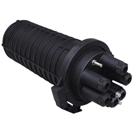
Importance of Splice Tray and Splice Closure
Whether it’s transmission, communication, or an intricate network of telemetry, splices, and dry closures serve as cornerstones to the optical fiber systems. Splice Trays provide predefined protection around the fibers minimizing interference due to bending moments or corrosion which is vital in preserving signal integrity. Due to these features, these trays are usually able to accommodate 12 to 24 splices over a larger network without any data loss.
Modern splice closures are far superior in construction, often capable of functioning in melting heat of +75ºC and freezing arctic conditions of -40ºC, along with both in-line and butt configurations which belt them unparalleled in multi-purpose deployment. On top of providing dust and moisture shielding closures can seal air-tight guaranteeing splice point integrity for many years to come.
When used in conjunction with each other, splice trays and splice closures are vital components for maintaining the performance, dependability, and durability of fiber optic networks. Their combination is crucial in supporting modern telecommunication systems that are high-capacity and latency-sensitive because it help preserve the integrity of the network even in harsh environments.
How to Minimize Splice Loss in Fiber Optic Splicing?

Techniques for Reducing Splice Loss
To guarantee optimal network performance and effective signal transmission, splice loss must be reduced during fiber optic splicing. The tips below will help you minimize loss during splicing.
Clean Fiber Cleaving
To increase the quality of the fiber splice in an optical fiber system, achieving a clean and smooth fiber cleave is very important. Utilization of appropriate cleaver is important to ensure the fiber end faces are perpendicular to the fiber axis with an angle of 90°. If the angle is not set accurately, the optical loss will occur in the joint fiber splicing process, with most accepting cleave angle error set to less than a 1-degree angle.
Set Up Proper Fusion Splicing Parameters
Setting arc power as well as the splice time for the different fiber types is critical in minimizing splice loss, thus proper fusion splicing parameters should always be set. Following manufacturer guidelines for single-mode or multimode fibers is always recommended because it helps to minimize loss from the fusion process. These days, with new progress in splicing technology, these parameters can be preset and adjusted automatically depending on the fiber characteristics. As a result, the average splice loss is about 0.02 dB for single-mode fibers.
Fiber Cleaning and Preparation
Most contaminants not limited to dust, oil, debris, or grime on the surface of a fiber can result in light attenuation at the splice point. The fiber ends must be cleaned with isopropyl alcohol and lint-free wipes so that they are devoid of contaminants. Cleanliness is particularly important in areas with densely packed fiber connections.
Optimal Alignment of Fibers
High-precision fusion splicers that have core alignment technology are crucial to splice loss mitigation. Core alignment refers to the matching of the two fiber cores during the splicing of two pieces of fiber. Modern splicers utilize profile alignment system (PAS) technology which saves alignment errors and averages splice loss to 0.01 to 0.05 dB.
Environmental Control
Splicing done in an improperly controlled environment may be influenced by external factors such as wind, heat, temperature changes, and humidity which cause misalignment or contamination. Portable splicing workstations, also known as field workstations, that have dust covers enable a relatively stable working environment in field conditions.
Regular Maintenance of Splicing Equipment
Calibration and maintenance of splicing equipment ensures that electrodes are cleaned and the cleaver blades are checked for quality. Worn-out or contaminated tools can impede performance and increase splice loss thereby losing the efficiency of the fiber optic network which is critically dependent on speed.
Applying the Best Materials Available
The first step towards achieving reduced splice loss is to make sure that side losing standard industry fiber optic cables, splicing sleeves, and connectors are used. Poorly crafted materials usually contain many flaws that may compromise the quality of the fiber splice to a great extent.
Testing and Validation After the Splice
After splicing is done, testing procedures like the Optical Time-Domain Reflectometer (OTDR) measurements need to be done to confirm the quality of the splice. The majority of jobs’ acceptable splice loss threshold is lower than 0.05 dB, which is why subsequent testing is important to tackle some problems that might be present without notice.
Through the application of these procedures, the technician achieves low-loss splices, which are needed to sustain the rapidly growing fiber optic networks that have high transmission speeds and low latency.
Maintaining Fiber Optic Integrity During Splicing
To keep splice joints lossless and optimally functional, fiber optics must be maintained with utmost care and precision during splicing. Here are some important pieces of advice and approaches that are supported by data to help keep fiber optics intact:
Cleaning Fibers With Proper Techniques
The splice loss can be significant due to dust, oil, and other material contaminants on the fiber end-faces. According to the set guidelines, cleaning the two fibers with 99% isopropyl alcohol and lint-free wipes guarantees great splice quality. Research demonstrates that uncleaned fibers lead to splice losses of more than 1 dB while cleaned fibers achieve losses of less than 0.05 dB.
Aligning Through Splicers with Precision
The new generation of fusion splicers employs core-alignment technology which makes sure that the two fiber cores are correctly positioned with respect to each other before being spliced. Their performance is known to be better than manual methods as core-alignment splicers have been reported to yield splice losses of over 0.02 dB. Such conditions are far better than those achieved by manual techniques due to misalignment losses.
Quality Control of An Environment To Be Used For Splicing
Some environmental conditions such as humidity or temperature excursions and dust can affect the quality of the splice. The use of splice enclosures or cleanrooms mitigates these external contaminants. For example, maintaining a temperature between 30 degrees and 15 degrees supports limiting the expansion or contraction of the fibers to ensure higher accuracy of their alignment.
Take Advantage of Quality Protective Sleeves
Mechanical overstress becomes a problem when fibers are not properly protected after splicing with heat-shrink sleeves or other mechanical protection. Studies show that spliced fibers that are not adequately protected during the weave or splicing process undergo tensile strain which degrades systems ability and reliability over time.
Proper upkeep of the equipment is also important for the effective functioning of the fiber splice processes.
Fusion splicers and cleavers are the two most used tools in fiber optics, and they need to be looked after if they are to perform superbly. Failing to replace dirty electrodes or dull cleaver blades will result in poor-quality splices. As per the manufacturers’ recommendation, replacing electrodes after 1,000 to 1,500 uses and periodically calibrating splicers will ensure low splice loss which them consistently.
Testing Using New Instrumentation
Splice testing with Optical Time-Domain Reflectometers(OTDR) and Power Meters confirms success. OTDR traces provide a deficit as well as other defects showing the information of the system after splicing, where a loss must always be below the level of 0.05 dB. Moreover, dynamic, real-time testing can change splicing input settings for the best optimization.
Following these techniques and using modern equipment allows service personnel and technicians to keep the network intact even under harsh conditions and guarantee the reliability required for the contemporary multi-operator fiber optic telecommunications network infrastructure.
What are the Applications of Splicing Fiber Optic Cables?
Telecommunication and Internet Infrastructure
In the world of telecommunications and data internet structure, fiber optic splicing is a necessity and it ensures reliable connections. Furthermore, it helps in the transfer of data over long distances without any signification loss in the signal which is extremely notable. In addition, splitting the device guarantees efficient communication on a global scale thus enabling broadband internet, voice calls, and video conferencing. Moreover, it maintains the stability and scalability of the network which meets the needs of modern digital communication systems.
Applications in Medical and Military Fields
Medical Applications
The healthcare field benefits from fiber optic technology through high-speed data transfer in telemedicine, remote consultations, and diagnostics. Spliced cables enable telecommunication between patients and providers. Fiber optics are integrated into real-time patient monitoring systems. Spliced cables enable uninterrupted signal transmission, ensuring accurate data relaying. Additionally, lasers and endoscopic devices that are essential in imaging and minimally invasive procedures rely on complete laser and fiber optic connections.
Juno Healthcare Center has augmented its capability with a new telemedicine service that allows patients from far and wide to have easy access to medical consultations.
- Surgical Devices: Surgical lasers depend on robust fiber optic connections for precise imaging.
- Endoscopic Procedures: Fiber optic splicing enhances clear visualization during minimally invasive procedures.
- Patient Monitoring Systems: Secure splicing guarantees accuracy and uninterrupted signal delivery.
- Telemedicine: Fiber optics enable fast, remote consultations and high-speed diagnostics.
Military Applications
Pinpoint surveillance and intelligence gathering are achievable through advanced sensor systems that rely on fiber optics. The technology is key in remote control equipment like unmanned aerial vehicles (UAVs), radar systems, and protected data transfer networks, serving as spliced fiber optic cables. These cables are robust enough to endure extreme environmental conditions present on the battlefield, providing dependability when needed most. Defense operations require performance, for which fiber optic splicing guarantees reliable communication systems.
- Radar Communication: Spliced cables ensure dependable data transmission in radar systems.
- UAV Systems: Strong links capable of supporting high-speed communication for drone missions.
- Secure Data Networks: Application of encrypted fiber optic channels for secure information transmission.
- Sensor Systems: Surveillance and intelligence gathering using fiber optics provides exceptionally detailed information.
Healthcare and defense applications are fulfilled by both industries through fiber optic splicing which provides the required reliability and connectivity.
Future Trends in Fiber Optic Technology
Advancements targeting the improvement of speed, efficiency, and accessibility within multiple industries are what describe the future of fiber optic technology. One clear example is the advancement of ultra-low latency fiber optics, which is necessary for next-generation 5G networks, cloud computing, and real-time data processing. This is certainly an evolution that seeks to keep up with the growing needs of rapid data transfer which is forecasted to reach 175 zettabytes by the year 2025.
Integration of quantum cryptography with fiber optic networks is another notable innovative area. This application not only assists in data encryption but helps protect the data from advanced hacking threats in the process which enhances cybersecurity. QKD or quantum key distribution is expected to improve sensitive communication within the government and financial sectors.
A more recent trend also includes the rise of photonic integrated circuits (PICs). These circuits combine several optical components into a single chip that contains a PIC, thereby drastically reducing the size, cost, and energy consumption needed while simultaneously improving the performance. PICs are regarded as essential to increasing the scaling of interconnectivity for data centers and high-performance computing systems.
In addition, the sustainability drive has encouraged the adoption of recyclable eco-friendly fiber optic cables. This innovation is in tandem with global efforts to reduce electronic waste, while still achieving high-performance standards, which cater to the environmental concerns regarding the growth of network infrastructures.
Finally, the growth of fiber-to-the-home (FTTH) technology continues, with predictions that more than 2 billion homes across the globe will have access to fiber-optic broadband by the year 2030. This growth will narrow the digital gap even further, enabling high-speed access to disadvantaged and remote regions.
These advancements in technology bring to the fore the innovations being made in fiber optics and give us a guarantee that this technology will continue to be at the center of a revolution in communication, security, and data management.
Frequently Asked Questions (FAQs)
Q: What is fiber optic splicing? Why is it important?
A: Fiber optic splicing is joining two fiber optic cables to form one continuous cable. As it applies to low loss and back reflection, splicing is important in fiber optic networks due to the signal quality and efficiency it enables within great distances.
Q: What are two of the most common methods of fiber optic splicing?
A: Fusion splicing and mechanical splicing are the most well-known methods of fiber optic splicing. In fusion splicing, an electric arc is utilized in a way that optical fibers are forced to melt together. Their connection is very low loss. Mechanical splicing does not employ the use of melting. Instead, it positions the fiber ends together using a mechanical fixture.
Q: How does fusion splicing work?
A: With fusion splicing, an electric arc is used to melt the ends of two inline fiber optic cables while they are aligned. The two melted ends form a single fiber after cooling down. A barrier-free joint with little optical loss and back reflection is produced which can be very useful for efficient operations.
Q: What tools are necessary for fiber optic splicing?
A: The required tools needed for fiber optic splicing are a precision cleaver to cut the fibers, fusion splicers to join the fibers with electric arcs, and splicing enclosures to cover the spliced fibers. Depending on the setup, pigtails and/or strippers may also be needed.
Q: What is ribbon fusion splicing and when is it used?
A: Ribbon fusion splicing joins several fibers at once so they can be fused more efficiently than individually. It is performed on ribbon cables and is typically used in settings where there is a large count of fibers needing to be spliced efficiently, such as data centers and outside plant installations.
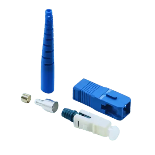
Q: What are pigtails in the context of fiber optic splicing?
A: Pigtails in optical fiber splicing are a few inches long fiber with a connector at one end and stripped at the other. Pigtails can be used to join optic fibers to devices or patch panels to simplify the management of fiber interconnections in the network.
Q: What are the benefits of using fusion splicers over mechanical splicing?
A: Fusion splicers are better than mechanical splicers because of the many advantages such as having lower optical loss, increased reliability over time, and lesser back reflection. These advantages make fusion splicing the most appropriate technique for effective splicing in fiber optic networks.
Q: How does splicing explain in terms of low loss and back reflection?
A: The term low loss splicing refers to the small amount of optical signals lost to attenuation at the splice point which greatly facilitates the transmission of signals through the spliced fiber parts. Good splices decrease back reflection which lets less energy return to the joint which can negatively affect the network.
Q: Explain the importance of having experience in the fiber optic industry as it relates to splicing.
A: Experience in the fiber optic industry matters for splicing because it is a very exacting science that requires skilled professional technicians to subsequently align and join the fibers flawlessly. Skilled technicians’ reliable splices, which are low loss and extremely accurate, ensure network integrity.
Reference Sources
1. Fiber optic grating inscription at the splice interface to measure strain and temperature
- Author: Shuanglu Zhang et al.
- Issue Date: 27th February, 2017.
- Citation Index: (Zhang et al., 2017)
Summary
- Main Results: This paper describes a new type of FBG inscribed over the splice interface of a thin core fiber and a standard single mode fiber which utilizes three reflection wavelengths. It has different sensitivities for temperature and strain and can therefore measure both simultaneously.
- Approach: The authors used the inscription of the Bragg grating phase mask to the FBG and utilized the refractive index changes between the fiber splices to obtain the sensitivity required.
2. Analysis of Effects of Attenuation on Fiber Optic Communication
Overview:
- Principal Conclusions: The article examines the phenomena of attenuation in optical fibers and particularly the role splices play in signal degradation. The research points out that the greater the distance between the transmitter and receiver, the greater the attenuation because of splice losses.
- Work Strategy: The authors executed a series of simulations to estimate the overall attenuation in fiber optic communications systems taking into account the number of splices, the distances between connections, and the length of the optic cable.
3. Measuring the Losses with an Alternative Fiber-Optic Fusion Splice Protection Method on the FUJICURA FSM 50S Splicer
Summary:
- Key Findings: This research quantifies the loss caused by different methods of protection in fiber optic fusion splicing. The standard method is shown to possibly cause additional loss during the closing phase.
- Methodology: The authors evaluate standard versus alternative sealing methods with the FUJICURA FSM 50S splicer by measuring the amount of attenuation created with each approach.
4. Optical fiber
5. Line splice
Post Views: 6,533


