The use of fiber optics has drastically changed the way data is sent, received, and processed. A lesser-known technological advancement in this space that remains unnoticed is the FC/APC connector. In this article, I will describe with utmost detail the FC/APC connector’s design, its role in fiber optic systems, and its advantages in comparison to other types of connectors. If you are an engineer, work in telecommunications, or wish to understand more about FC/APC’s relevance to modern infrastructure, you will learn the most important information through this guide.
What is an FC/APC Connector, and How Does it Work?
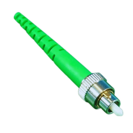
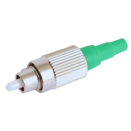
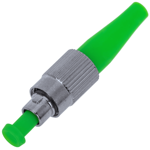
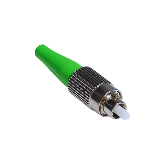
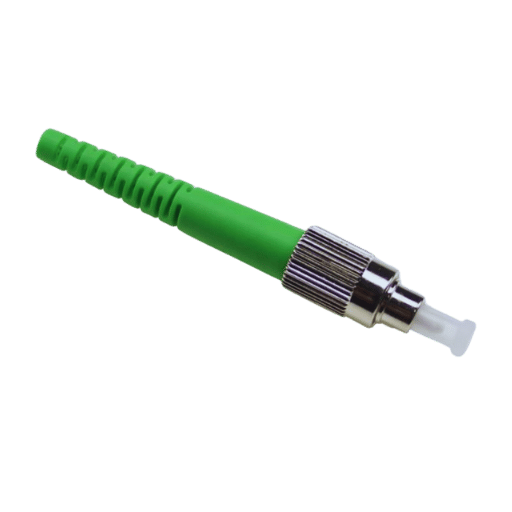
The FC/APC connector is uniquely designed for high-level optical signal transmission with a fiber optic connector. The letters in “FC” refer to the Ferrule connector, showcasing its strong threaded connection mechanism, while “APC” stands for Angled Physical Contact, a feature that reduces signal loss alongside minimizing the back reflection. Light is enabled through the files, and the connector’s ferrule end face is polished at an 8-degree angle, aiding in saving the light from reflecting straight back into the fiber. With such characteristics, the FC/APC connector is best suited for highly reliable and precise performance tasks in telecommunications, data networks, and high-measurement systems. Its durable structure makes sure that even in severe vibrations or movement of an environment, a secure connection is maintained which makes it useful in critical optical networks.
Understanding the Basic Components of the Connector
Optical connectors are specially made to permit accurate and effective transfer of signals with minimum losses throughout the entire process. Here are the important parts and their functions:
- Ferrule: The most central part of an optical connector is the ferrule, whose responsibility is to position the optical fiber to maximize transmission accuracy. The ferrule includes the optical fiber and guarantees its alignment relative to the surrounding components. The majority of single-mode fibers’ ferrule holes are 125 microns in diameter, which is fairly broad. Ferrules themselves are typically made from ceramic, metal, or plastic.
- Connector Housing: This part sits outside and serves as a protective shell enclosing the ferrule and other internal components. This part gives structural strength while providing security for the connector during mating and demating. Plastic or metal are the dominant materials used in this section because of their strong characteristic performance.
- Sleeve (or Adapter): The sleeve allows the two connected ferrules to be in precise alignment in a coupler or adapter. Insertion loss in high-performance connectors is lower than 0.3 dB, which is quite impressive and cannot be achieved without precision and high alignment.
- Boot and Strain Relief: The boot, together with other strain relief mechanisms, covers the point where the fiber cable meets the connector. It does not allow bending or pulling forces, which, if not restricted, can cause damage and misalignment of the fiber, which, in turn, reduces the performance of the entire device.
- Polish Type (e.g., PC, UPC, APC): The fiber or ferrule tip undergoes various polishing processes to decrease reflections and enhance signal clarity. For example, optical networks with high precision can utilize APC (Angled Physical Contact) as it has return losses of better than -60 dB.
Every single component is designed to serve a specific part of the composite figures to be measured, such as insertion loss, return loss, and life cycle. Connectors need to conform to industry standards like IEC 61754 or Telcordia GR-326, which establish accuracy limits and environmental performance standards to ensure robustness. Compliance with such standards makes them dependable for use in the provision of high-speed internet services, sophisticated data centers, and reliable and delicate networks.
The Role of Angled Physical Contact in Fiber Optics
Angled Physical Contact (APC) reduces signal attenuation and back reflection in fiber optics by ensuring that the fiber end faces are polished to an angle, usually 8 degrees. The angle improves the APC’s ability to deal with the return of reflected light and is ideal for preserving signal quality in high-density or long-distance communication systems. Telecommunication networks, optical amplifiers, and CATV systems are some of the industries that use the APC for high-performance and low-reflection applications. APC connectors are a standard choice in highly demanding fiber optic systems owing to the enhanced network reliability and transmission quality that they provide.
Key Differences Between Single Mode and Multimode Fiber
Core Diameter
- Single Mode Fiber: Its core diameter is smaller, approximately 9 microns.
- Multimode Fiber: Its core diameter is larger. Generally 50 or 62.5 microns, enabling the propagation of several light modes.
Wavelengths Used
- Single Mode Fiber: Generally works at higher wavelengths like 1310 nm and 1550 nm.
- Multimode Fiber: Mostly works at shorter wavelengths: 850 nm and 1300 nm.
Transmission Distance
- Single Mode Fiber: Ideal for long-range communications, frequently more than 40 kilometers due to low signal loss.
- Multimode Fiber: Intended for shorter-range use, generally confined to a few hundred meters because of greater signal loss and modal dispersion with distance.
Bandwidth
- Single Mode Fiber: Provides virtually no limit on bandwidth which is custom for high-speed and high demand usage scenarios.
- Multimode Fiber: More modal dispersion results in low bandwidth making it not ideal for high data rate or long distance applications.
Cost
- Single Mode Fiber: Usually more costly for its construction owing to stringent manufacturing processes and the need for laser transmitters.
- Multimode Fiber: Cheaper to manufacture and deploy, using low-cost LED light sources readily makes it more economical.
Light Source
- Single Mode Fiber: Includes lasers, which are used for high accuracy and coherence light sources, making them suitable for remote transmission.
- Multimode Fiber: Commonly utilizes LEDs or VCSELs (Vertical-Cavity Surface-Emitting Lasers), which have lower cost but lower accuracy.
Applications
- Single Mode Fiber: Commonly used in major telecommunication networks, WANs (Wide Area Networks), and data centers.
- Multimode Fiber: Used widely in Local Area Networks (LANs), data storage networks, and short-range audio/video transmission.
Signal Dispersion
- Single Mode Fiber: Has very little modal dispersion and so provides clear and stable signals even over long distances.
- Multimode Fiber: Suffers a lot from modal dispersion, making the effective distance and bandwidth of the fiber limited.
Equipment Compatibility
- Single Mode Fiber: Uses very advanced and expensive equipment like high precision transceivers, which are not easily available.
- Multimode Fiber: Uses less sophisticated and cheaper equipment, which makes it more widely used for low budget projects.
These distinctions help network designers choose the appropriate fiber type according to performance requirements, cost, and distance.
Why Choose FC/APC Connectors for Your Fiber Optic Needs?
Advantages of Using APC Connectors Over UPC
Reduced Optical Return Loss
- Connectors of APC (Angled Physical Contact) type are constructed to achieve lesser optical return loss. The back reflections from the angled end face of the APC connector are reduced, with return losses often exceeding -60 dB. This enables their use in applications that have stringent requirements for the integrity of signals, such as in data centers, PONs, and even telecommunications over long distances.
Enhanced Signal Quality
- The other peripheral angle reflection loss by these APC connectors is a part of the host or main signal. This is very important in zero to low signal interference areas like video transmission or FTTH environments.
Suitability for High-Power Applications
- These connectors will be able to handle high optical signals with greater ease. The lower reflective losses ensure that breakdowns caused by back reflections will rather be minimal which could create problems for sensitive equipment and hence result to degrading system performance in high power optical setups.
Improved System Stability
- Connectors as those with angled polish will perform better than the others with regards to their resistance to vibration or thermal imaging. APC connectors are more stable with systems that have environmental issues affecting their performance.
Adherence to Industry Regulations
- In order to ensure network efficiency, several international standards suggest the use of APC connectors in certain applications. For instance, CATV (Cable Television) networks situated in the RF spectrum have increased requirements for APC connectors to guarantee unobstructed and interference-free signal transmission.
Reduced Crosstalk
- Owing to their design, APC connectors provide better isolation and communication for crosstalk mitigation between close fibers in dense wavelength-division multiplexing (DWDM) systems. This makes them suitable for designs where precise signal separation is critically important.
APC connectors offer unmatched results for signal quality, stability, and efficiency compared to UPC (Ultra Physical Contact) connectors in demanding applications. These features underscore the importance of modern fiber optic systems where performance and reliability are central components.
How the Ceramic Ferrule Enhances Performance
The ceramic ferrule is one of the most crucial parts of a fiber optic connector as it provides the alignment needed for the optical fibers to be placed and held in line with phenomenal accuracy. This alignment minimizes signal loss while maximizing connection reliability for many applications. The main benefit of ceramic ferrules is their material, which is composed of zirconia. Zirconia is an advanced ceramic material that is renowned for its hardness, thermal stability, and anti-wear properties.
Zirconia’s low coefficient of thermal expansion guarantees reliability within a wider temperature range, lessening the chances of alignment misplacement due to thermal fluctuations. In addition, ceramic ferrules are capable of achieving extremely precise tolerances, normally less than 1µm. Such tolerances are instrumental to the accurate alignment of fiber cores when connectors are mated. With these tolerances, extremely low insertion loss of about 0.2 dB is common, as well as return loss values above 55 dB with APC connectors and greater than 50 dB for UPC connectors. Return loss for UPC connectors tends to be above 50 dB. These parameters are essential in efficient communication networks, particularly in the systems of Dense Wavelength Division Multiplexing (DWDM), where the signals need utmost integrity.
Furthermore, ceramic ferrules are unique in their durability and resistance to overheating as well as contamination, which ensures consistency over time in fiber optic connections. This ability to endure many mating cycles without substantial degradation helps to prevent excessive spending through lower maintenance and replacement costs. Given the rising need for higher bandwidth-enabled reliable data transmission, the incorporation of ceramic ferrules has greatly improved the performance and longevity of fiber optic infrastructure in telecommunications, data centers, and enterprises.
How to Install an FC/APC Fiber Connector
Step-by-Step Guide to Connector Installation
Step 1: Prepare the Fiber Optic Cable
- Using a fiber optic stripper, remove the protective outer jacket from the fiber optic cable to begin exposing the bare fiber optic cable.
- Wipe the exposed fiber with an alcohol wipe to ensure dust, dirt, and contaminants are removed.
- Make sure the cable length is appropriate for the design of the connector.
Step 2: Install the Crimp Sleeve
- Prior to starting the assembly of the connector, crimp sleeve or boot should be placed over the fiber optic cable.
- Crimp sleeves may require slight adjustments later, so make sure they are properly positioned to avoid this problem.
Step 3: Insert the Fiber into the Connector
- Place the prepared fiber in the center hole of the ceramic ferrule of the FC/APC connector firmly, taking care not to lose signals and achieve the best possible results.
- Insertion of the fiber into the connector should be executed with moderate force to avoid potential damage. Make sure the fiber moves to the correct depth.
Step 4: Secure the Connection
- A crimping tool specifically meant for the FC connector type should be used to ensure the sleeve is firmly secured onto the fiber optic cable.
- Confirm the cable attachment to the connector to ensure stability during and after usage.
Step 5: Cleaving and polishing a fiber
- A proper cut of the exposed fiber should be made using a high-precision fiber cleaver. The aim is to achieve a clean and flat fiber end face.
- To achieve optimal performance, polish the fiber end face using either a polishing film or equipment designed for APC (Angled Physical Contact) terminations. An 8-degree angle must be produced.
Step 6: While Using a Fiber End Face Microscope
- Examine the polished end face under a fiber optic inspection microscope for scratches, dust, and other imperfections.
- As necessary, adjust until the quality and performance of the connector meet industry standards.
Step 7: Test the Connector
- To check for signal strength and insertion loss, connect the assembled FC/APC connector to a power meter or light source.
- Verify to ensure the readings are within the limits that are acceptable depending on the application, as well as the technical specifications.
Step 8: Finalize and Secure the Installation
- With the fiber protected and strain relief provided, slide the crimp boot into place.
- For labeling or documentation purposes, the connector installation can be noted for future reference or maintenance.
These steps will allow for a precision installation of an FC/APC fiber connector allowing for optimal connection stability and performance in advanced fiber optic systems.
Importance of Proper Strain Relief in Installations
Fiber optics cables and components must have an adequate strain relief mechanism installed in order to protect them from enduring mechanical forces in the long run and guarantee proper performance. Strain relief describes the prevention of a mechanical force, such as pulling, bending, or twisting, from being transferred to sensitive internal components like fiber cores, connectors, or soldered points. Throughout time, lack of accompanying strain relief renders the cable assembly exposed to certain forms of damage, such as increased insertion loss or signal degradation, which ultimately worsens the condition of the system.
Recent studies in cable durability have found that not applying the proper strain relief mechanisms causes the cables to have a defined lifespan which is up to 50% less than its normal lifespan. For instance, some data suggests that fiber optics cables which are repeatedly bent without adequate strain relief experience higher failure rates when sent through mechanical integrity testing than those with proper reinforcement. Furthermore, there are already established norms within the industry, like the ones set by the Telecommunications Industry Association (TIA), where immediately using couching frames or other strain relief mechanisms is suggested in order to satisfy the durability and reliability requirements in more severe environments.
Installers need to utilize excellent crimp boots, cable clamps, or flexible sleeves specific to the cable type and application for optimal strain relief. Additionally, ensuring that cables are routed without excessive sharp bends or preferably within the bend radius given by manufacturers is essential to reducing risk. By doing so, these measures together with strain relief principles will improve the reliability of installations and reduce expensive repairs or replacements.
Tips for Ensuring Low Insertion Loss
Insertion Loss has severe implications on system or channel performance as it indicates the signal loss that occurs during cable insertion. To achieve optimal system performance while minimizing insertion loss, the following practices should be undertaken:
Choose Appropriate Materials
- Use low resistance cables, connectors, and adapters. For example, RF applications with coaxial cables that have silver plated conductors and low loss dielectric materials provide minimal insertion loss.
Keep Matching Impedance
- It is very important to match the impedance of the transmission line, source and load. Signal reflections which increase insertion loss may occur from mismatched impedances. Standard impedance of 50Ω or 75Ω for RF systems should be maintained to minimize losses and reflections.
Improve Connector Selection
- Poorly designed connectors and improperly terminated connections increase insertion loss. It is advisable to use precision connectors that consistently guarantee tight connections. High frequency applications for SMA and N-Type connectors offer low loss and better performance.
Reduce the Length of Cables
- To decrease signal loss, cable runs must be minimized, and because insertion loss is tied with the length of a cable, it can be kept short. Single mode fibers are remarkably advantageous as fiber optic cables lose approximately 0.3 dB per kilometer.
Care for and Inspect Connectors & Cables
- Regular maintenance helps to clean the connectors and prevents debris or oxidation from cutting down the signal. A dirty or corroded connector can dramatically increase Insertion loss for some cases up to 1-2 dB, especially at higher frequencies.
Supervise Operating Frequency
- Greater frequencies generally incur a higher degree of Insertion loss due to the skin effect and other properties of the material. For example, coaxial cables could display an increase of Insertion loss moving 0.5 dB per 100 meters at 100 MHz to more than 3dB per 100 meters at 2GHz. This impact can be reduced by choosing cables that are rated for certain frequency ranges.
Invest in More Sophisticated Testing Devices
- Contemporary VNAs and OTDRs measure insertion loss with great accuracy. An even greater effectiveness would be achieved through ensuring minor losses are dealt with in advance before deployment. Many systems need to follow the allowance for losses, which is stated to be under 3dB.
Using these strategies, system designers and installers can minimize the insertion loss, thereby maximizing signal transmission in conjunction with system longevity across diverse applications.
Common Issues with Fiber Optic Connectors and How to Solve Them
Troubleshooting Connection Problems
Contamination of Connectors
- As with other types of connectors, dirty fiber optic connectors will result in poor connections. Use fiber optic cleaning tools, or if necessary, use lint-free wipes and isopropyl alcohol to clean the connectors. Always check the connectors visually before reconnecting.
Misalignment of Connectors
- Disruption within signal transmission can result from misaligned connectors. Check the alignment of the two connectors using a visual fault locator (VFL) or alignment tools suitable for the type of connectors in use.
Broken Connectors or Cables
- Any physical damage to the connector or cable, such as cracks and bends, results in degradation of connection quality. Look for any signs of damage, and once you see any, change the damaged elements without delay to minimize continuous signal loss.
Improper Mating of Connectors
- Locking mechanism on connectors must be positively closed. Loose connections are prone to intermittent signal issues. Examine the mating mechanism, and if required, re-seat the connector.
Errors Relating to Cable Polarity
- Improper polarity can stop the signal from flowing. Check cable polarity using a polarity tester to make sure that the transmitter and receiver connection is not reversed. Change the connections to meet the configuration.
By tackling these issues in an organized manner, the optimal performance of the fiber optic connections could be restored with minimal downtime.
Dealing with High-Vibration Environments
It is extremely challenging to maintain stable fiber optic connectivity in high-vibration environments. To mitigate these challenges, you can:
Use Ruggedized Connectors
- Utilize connectors that are specifically tailored to withstand high-vibration situations. These connectors are equipped with robust locking mechanisms to avoid disconnection.
Employ Strain Relief Methods
- Add strain relief features like cable clamps or flexible boots to help reduce the amount of stress placed on the cables due to repetitive vibrations.
Secure Cables Properly
- Cables must be restrained securely using brackets, ties, or other management devices to eliminate unnecessary movement while also preventing over-bending and over-tensioning.
Periodic Inspections
- Intermittently check connections and cables for signs of wear and tear due to vibration. Fatigue prone parts should be replaced to sustain dependability.
These measures will increase the longevity and reliability of fiber optic connections in high-vibration environments, subsequently increasing service availability while decreasing system deterioration.
Exploring the Different Variants of FC/APC Connectors
Simplex vs. Duplex: Which Fiber Optic Connector is Right for You?
Both simplex and duplex fiber optic connectors may be implemented depending on the data transmission needs of your system:
- Simplex Connectors are appropriate for the transmission of data to one direction only and operates on a single fiber. It is best suited for applications that entail the transmission of only a single signal at a time which includes certain sensors or monitoring systems.
- Duplex Connectors allow data transmission on two fibers—one for sending and the other for receiving. This type of connector is needed for communication systems that require two-way communication simultaneously. Examples of such systems are Ethernet networks.
Choose simplex for unidirectional tasks and duplex for systems requiring full-duplex communication. It is important that the choice is consistent with your system functionality and performance requirements.
The Impact of 8° Pre-Angled Polishing
By setting the end face of the fiber connector at an 8-degree angle, back reflections can be lowered significantly with the use of the 8-degree pre-angled polishing technique. This method makes it possible to offset all contributing light interference to the fiber core, thus guaranteeing fewer signals. For precise and efficient optical systems, this technique is more useful and effective. Most 8° pre-angled connectors are utilized with single-mode fibers, which are able to improve return loss. This improvement leads to an overall enhancement in data transmission reliability and quality.
Frequently Asked Questions (FAQs)
Q: What is an FC/APC connector?
A: An FC/APC connector is a kind of fiber optic connector that employs a screw-on type mechanism and has an angled physical contact. The angle polish on the fiber end is designed to minimize the signal loss caused by the light reflecting back up the fiber.
Q: How does the FC/APC connector differ from other connectors?
A: The FC/APC connector differs from others via its screw on the connector’s body, which gives a more secure and stable connection. The end of the fiber is polished at an angle to help minimize back reflection, which makes it appropriate for singlemode applications.
Q: Why is the angle polish important in FC/APC connectors?
A: The angle polish in FC/APC connectors makes it so that the surfaces of the two interconnected fibers must be glued together and, as they reflect light, at an angle. This makes it possible to minimize back reflection, which is particularly important when it comes to signal quality in singlemode fiber applications.
Q: Can FC/APC connectors be used with both ø2 mm and ø3.8 mm tubing?
A: Certainly, FC/APC connectors are adaptable to both ø2 mm tubing and ø3.8 mm tubing which allows for the different cable diameters to be accompanied and helps maintain a secure and reliable connection.
Q: Are simplex singlemode fiber systems compatible with FC/APC connectors?
A: The FC/APC connectors are indeed compatible with simplex singlemode fiber systems as they facilitate a stable connection with minimal signal loss.
Q: Are FC/APC connectors available without fiber cables?
A: Yes, you can purchase FC/APC connectors independently, enabling you to create personalized configurations and replace components as you see fit.
Q: What is the typical timeline for receiving FC/APC connectors after purchase?
A: Processing and shipping orders for FC/APC connectors may take up to a week because it depends on stock levels and your location.
Q: What are the uses of FC/APC connectors?
A: Yes, FC/APC connectors are ideal for polarization maintaining applications because they offer stable alignment which makes it possible for the surfaces of two fibers to be aligned accurately.
Q: Is there any tool I need that would make changes to an FC/APC connector easier?
A: Yes, changing connectors to FUC/APC requires the right tools for screw-type connections to firmly secure the connector to the fiber.
Q: Is it possible to make custom patch cables with FC/APC connectors incorporated?
A: Yes, custom patch cables can still be made with FC/APC connectors that either come pre-assembled from this page or are put together according to your requirements.
Reference Sources
1. Title: Examination of temperature impact on optical connectors’ performance
- Authors: Tomáš Kajnar et al.
- Publication Date: 2015-01-06
- Citation Token: (Kajnar et al., 2015)
- Summary: This paper describes the influence of temperature on the operational effectiveness of optical connectors, with emphasis on return loss and the attenuation coefficient pertaining to various types of connectors, including the FC/APC type. The study demonstrates the need to quantify thermal effects on connectors’ performance to maintain optimum optical communication systems. The methodology used involved statistical analysis of return loss for multiple temperature steps.
2. Title: Evaluation of the Effective Fiber Optic Tip Used In Interferometric Displacement Measurement
- Authors: E. A. Moro et al.
- Publication Date: 2011-01-24
- Citation Token: (Moro et al., 2011)
- Summary: The optical components were placed into the cavity of an interferometric displacement sensor, and their performance with respect to the sensor measured was evaluated. This study focuses on the effect design of fiber optic tips, such as FC/APC connectors, on the measurement’s accuracy and sensitivity. The methodology consists of experimental arrangements with variable values for the intensity of the reflected light at specific wavelengths, where the performance of different types of connectors was analyzed.
3. Title: A Comparison of Performance in Passive Optical Networks Using UPC and APC Connectors
- Authors: V. O’Byrne et al.
- Date of Publication: 03/06/2005
- Citation Token: (O’Byrne et al., 2005)
- Summary: This paper analyzes how the performance of UPC and APC connectors differs in passive optical networks (PONs). It focuses on the superior performance of APC connectors in mitigating reflections and enhancing signal quality. The methodology used included experiments measuring signal quality with various network topologies.
4. Title: Temperature sensing based on multimode interference in polymer optical fibers: sensitivity enhancement by PC-APC connections
- Authors: Kun Wang et al.
- Date of Publication: 10/056/2022
- Citation Token: (Wang et al., 2022)
- Abstract: This work describes a temperature sensor based on polymer optical fibers with PC-APC connections, using and improving upon the design. The results show that incorporating PC-APC connectors greatly enhances the sensor’s temperature sensitivity. The methodology consists of defining experimental arrangements to test the temperature-sensing characteristics of the various connectors.
5. Electrical connector
6. Optical fiber connector
7. Optical fiber
Post Views: 6,897


