The C19 outlet is integral in the field of power distribution, particularly in industries and data centers where efficient and reliable power connections are of concern. As it is designed to meet the needs of high-powered devices and equipment in this case, it seeks to keep a stable supply of electricity concerning them Well in this guide. Hence, we are going to talk about these outlet types in detail, describing their features C19 outlet, usage in different power distribution systems the advantages of using such outlets, and the circumstances under which they are most useful. Using the technical approach, this paper will seek to explain to the reader how C19 outlets assist in the operation of electrical systems that demand complex interconnectivity.
What is a Rack PDU and How Does It Work?
A Rack PDU (Power Distribution Unit) is defined as a physical structure embedded within the data center that provides power to several devices that can use it from a single source of power input. It does so by collecting power through the mains and feeding it through a high-power socket, generally a C19. This power is then supplied through high dynamic range output ports, which enables proper organization and distribution of electric power to attached devices that are usually servers or networking applications. Its construction guarantees maximization of the regulation as well as the monitoring of the energy supplied and consumed, improving energy utilization and normal operations.
Understanding the Basics of a Rack PDU
One of the most important components of a data center is a Rack Power Distribution Unit (PDU), which has the responsibility of energizing and interconnecting plenty of different devices. Among them are power capacity management, supervision of energy use in real-time, and the ability for remote control.
The functionality of a Rack PDU starts from its power capacity ratings, which are mostly expressed in kilowatts (kW) and represent the highest amount of electrical load the equipment can manage efficiently. Other than simple power distribution, more advanced PDUs can incorporate meters that accurately capture the amount of energy consumed in real time. This power-oriented approach makes it possible to manage and optimize energy use more effectively, with the potential of cutting down on costs by eliminating wasteful power consumption practices.
Also embedded in the unit are typically network or serial ports that allow remote management of the PDUs, monitoring, and control of the units over a network. This aspect is especially important in new generation data centers that wish to carry out operations without any unexpected hitches and are quick to respond to any threats to power availability. Other than that, PDUs are also made to be used with certain redundancy features, such as dual circuit design to avoid interruptions in the power supply in the event of maintenance and or power failures.
Continued implementation of these engineering features regards Rack PDUs as relevant in data centers to aid in boosting the resilience and/or efficiency of the system. With smart monitoring and control systems incorporated in data centers, PDUs can not simply be used as power distribution devices but as one of the devices to assist in making sure operations are efficient and reliable.
How Does a C19 Outlet Fit into a Rack PDU?
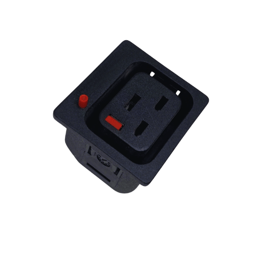
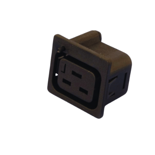
Essential elements in Rack PDUs are the C19 outlets, as these outlets are one of the universal outlets used to connect high-powered equipment. This receptacle receives C20 plugs, thus providing an electrical point as well. This receptacle is designed to aid devices that need a higher amperage than most normal shafts, which is generally pegged at 16 Amps for enterprise servers and other critical server-grade IT peripherals. Making the Rack PDU design allows the effective use of technology as power can be distributed within the data center to the devices, ensuring that they operate optimally with robust power for their connections.
Benefits of Using a Rack PDU with C19 Outlets
Modern-day data centers obtain certain benefits from the use of Rack PDUs with C19 outlets. To begin with, they allow for higher power density without the requirement of heavy rewiring or making more infrastructure changes by offering more versatility in how power can be provided to high-power devices. This aspect is very critical for places with varying amounts of power demand. In addition, C19 outlets help enhance load balancing by accommodating larger current levels, making it possible to optimize power consumption across devices, thereby reducing the likelihood of circuits getting excessively loaded and making them stable and safe. Lastly, Rack PDUs equipped with C19 outlets also promote energy use efficiency since they enable power management, and data centers do not have to rack up unnecessary energy bills. All of these advantages together promote uninterrupted performance, expandable opportunities, and dependable operation of the infrastructure of the data center.
Why Are C19 Outlets Crucial in Power Distribution?
The Role of C19 and C13 in Power Systems
C19 and C13 power outlets are critical components of power systems particularly in data centers. The C19 power input sockets are mainly purposed for high-capacity equipment and can supply up to 16 Amps, thus fitting servers and other essential IT devices in the enterprise level. The C13 outlets, however, supply less than 10 Amps and serve the low-end workstation and peripherals. They all assure high efficiency and flexibility in powering diverse electrical devices without extensive system modifications, improving operational reliability and safety.
Understanding C19 Outlet Specifications
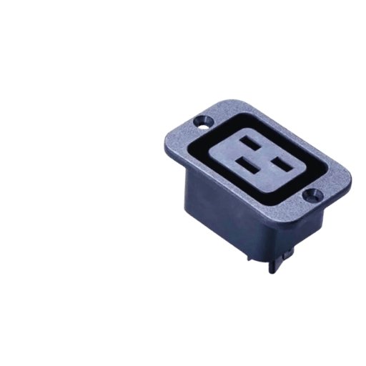
The dimensions of C19 outlets are based on IEC 60320 and allow higher power cables and heavier equipment. The approximate dimensions of the female connector are 30mm x 22.5mm with a depth of around 12mm, where normally an IEC 60320 C20 male plug is inserted. These sockets are made to have mains at voltage ratings of two hundred and fifty volts with a current rating of sixteen amperes, which justifies their use in high-powered apparatus. In addition, C19 outlets are built strong enough to be able to endure the heat and constructional strain that accompany the use of high powered equipment. Such a design also enables them to be important supporting structures for the power system within a data center, where efficient and dependable power distribution is essential.
Comparing C19 with C20 Connectors
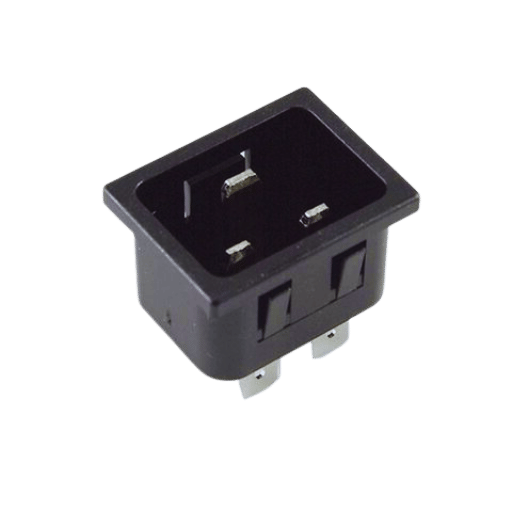
While a C19 connector can be understood as the power outlet, the C20 type can be described as the gosh plug or the power inlet. Pen points of the juxtaposition will be:
Design and Dimensions:
- C19 female connectors dimensions in normal case will be 30mm X 22.5mm with a depth of 12 mm.
- C20 male connectors are designed to these dimensions to promote an accurate and correct positioning of male C20 plug into female C19 socket as there is a standard size compatible with the C19 sockets.
Electrical Ratings:
- Commonly both the C19 and C20 connectors are rated up to 16 Amps and can take a maximum nominal voltage of 250 volts which is supportable for high power consuming equipment.
Application:
- C19 connectors are a common appliance for use in power strips, power distribution units, uninterruptible power supply used in office buildings.
- C20 connectors are found on the power cords of servers, networking devices, and other IT equipment and are capable of plugging into C19 sockets.
Construction:
- Both connectors are constructed to deal with high electrical energy levels and they utilize materials which are resistant to the thermal and mechanical requirements presented in data centers and critical IT systems.
Standards:
- There is also the conformity regarding the IEC 60320 with the knowledge of the two standards and hence regional variations, this restriction enhances regional globalisation of safety compliance of particular electrical components.
Attributes put forward demonstrate that the C19 and C20 connectors are fundamental in enhancing power management and distribution systems in high performance computing environments.
How to Simplify the Installation of C19 Outlets?

Step-by-Step Guide to Installing a Panel Mount Power Outlet
- Gather Materials: Get a C19 /C20 panel mounted socket, required instruments like screwdriver, pliers, and wearing head protection and gloves.
- Safety Comes First: Always ensure all power supplies are disconnected as a precaution against shock or injury during operation.
- Prepare the Mounting Area: Decide the point of installation and apply a marker on the panel where the cabinet outlet will be installed as per the measurement of the connector.
- Cut the Opening: Appropriate cutting tools should be employed to cut out the mounting hole to the right measurement so that it just perfectly accommodates the connector.
- Install the Connector: Fix the connector in the prepared hole and ensure that it remains in place, using screws or a lock in position system.
- Wiring: Live and neutral and ground wires should be connected respectively to the appropriate terminals of outlet sockets according to wiring standards.
- Secure Connections: Clean and tighten any screws to prevent damages or loose contacts for long-lasting socket connections.
- Test the Installation: Switch on the electricity and check the outlet by means of the wire disruptive device fast for testing correctness of its operation safety.
Ensuring Proper Grounding and Connection
To guarantee electrical safety as well as that of consistent performance in every installation, it is necessary to have the correct grounding and connections done. To make the grounding effective, ensure the grounding wire is connected to the prescribed terminal on the outlet. A multimeter should be used to test the continuity of the earth terminal of the outlet and the main grounding terminal of the power distribution unit or electrical panel. This ensures that in the event of a fault, the current finds a short circuit to ground, thereby preventing any electric shock or damage to the equipment. Lastly, do not forget to visually include that wear and tear of any of the connections or corrosion has happened and that every conductor has been properly terminated without any exposed wire at the ends.
Troubleshooting Common Installation Issues
Whenever there are installation challenges, there are simple problems that can be fixed to guarantee a successful installation. First, check if the power source is working and properly set to the outlet using the voltage tester. A power loss could point towards a breaker in the off position, a blown fuse, or some wires that are not right. Second, all connections must be made firmly, and the multimeter must be used to check for continuity across the connections, most especially where electrical wires connect since being loose or wrongly connected would lead to electrical malfunctions. Where power is still an issue, inspect the wires or connectors for physical damage, including but not limited to cuts and even corrosion, as damaged connectors are, in most cases, unusable and should be changed. Last, make sure that the electrical fittings that have been made adhere to local and national code compliance, as any failures in this area can cause system failures or safety concerns. By following these steps, you are able to troubleshoot and resolve electrical installation problems in the most effective way possible.
How to Ensure Your PDU Meets Specification Standards?
Understanding IEC 60320 Specification
The IEC 60320 is a universal power supply cable international standard that defines connector and inlet types to ensure interworking and integration safety for electrical devices. These standards are especially important in professional and industrial environments where risk and safety must be effectively managed. Connectors of the IEC 60320 standard can be grouped into various types which are known using their letters there are C5/C6, C13/C14, and C19/C20 connectors. Each type possesses various current and temperature ratings. In this case, the C13 connector can allow currents of up to 10A while connected to a voltage of 250V, whereas the C13 connector is widely used in a computing environment to connect and supply power to desktop computers and servers. The specification offers instructions on how the equipment should be arranged, how various holes will be oriented, as well as the degree of fabrication temperature, but it also offers designs for cables that operate at higher temperatures for products that create more heat. This makes it possible respectively to utilize devices designed according to the IEC 60320 requirements for any commercial and residential units in different world regions without the trouble of designing several types of power supplies. Compliance with these requirements makes it possible to provide interoperability, simplify the foreign trade of countries, and join global standardization in the design of electrical equipment.
Importance of Universal Power Compatibility
Most manufacturers in the world are focused on improving efficiency and increasing the level of safety of electrical devices in different countries. Philip Turner suggests this can be achieved by specifying IEC 60320 power connectors and other related specifications to assist manufacturers in the design of various forms of the product that arises from mass production in the appropriate regions. This standardization guarantees that equipment can be used without any vigorous issues across a number of electric situations, thus helping to limit the inept performance of the device that could cause an accident. Furthermore, it enables the smooth conduct of foreign trade by making the supply chain less complicated, cuts down the amount of funds spent on storehouse management, and helps introduce new products to the market quickly. It also acts to promote uniform standards of quality and reliability irrespective of geographical markets, enabling every consumer to worry less about the differences in electric supply in some territories.
Testing and Verifying Power Distribution Specifications
Testing and verification of power distribution specifications is one of the most important steps in making electrical systems safe, reliable, and effective. It usually consists of a number of major stages:
- Compliance Testing: It includes evaluation of the compliance of power distribution equipment with appropriate standards such as IEC 60320 Compliance tests. Often compliance tests involve checking the specific electrical and mechanical characteristics of the equipment according to the requirements of a given standard.
- Performance Testing: Both qualitative tests and operational tests are developed where the equipment will be utilized in various loadings. This aids in exposing the adverse aspects of the power distribution design which should be addressed.
- Safety Testing: Safety tests are performed against the threat of electrical shocks caused by the power distribution units. These include short circuit and overload and insulation resistance tests.
- Environmental Testing: The power distribution unit is subjected to environmental abuse tests to ensure its expected functioning in actual practice. This includes a temperature, and humidity, vibration tests.
- Interference Testing: Testing of the power distribution unit for electromagnetic interference is also carried out to prevent its emission or acceptability of excessive electromagnetic interference so that other devices could operate unaffected.
With these testing protocols, manufacturers can certify that their power distribution systems are sound and conform to all relevant specifications including the safety and performance of power delivery to apparatus around the world.
What Are the Best Practices for C19 Outlet Maintenance?
Regular Inspection and Testing of C19 Outlets
Scheduled evaluation of power C19 sockets, along with timely C19 sockets and connection testing, helps maintain and protect the reliability of power distribution. The given steps give further details of how optimal maintenance can be performed:
- Visual Inspection: This involves checking the physical shape of C 19 for signs of damage such as abrasion, melting, discoloration, bulging, or anything uncharacteristic of a normal condition. Attention also has to be focused on the plug and socket in case some contacts are not in place or there are some broken connections.
- Electrical Testing: There is a necessary routine for evaluating electrical testing so that it can be assured that the outlet functions within the fixed specified allowance conditions for any given circumstances. This includes checking the output of voltage and current to realize whether they are within acceptable limits, 250V for voltage and 16A for the current, in most cases. Also, continuity tests are able to be performed to check that there is no break in the connection of the complete circuit repetitively.
- Load Testing: Load tests assess whether these outlet sockets are capable of blowing out the overload rating without failure. These tests mimic peak load provisions and therefore would seek to root out any deficiencies in the outlet’s configuration when under peak electrical loads.
- Insulation Resistance Testing: Electrical insulation tests are done to establish that enough electrical insulators separate metallic parts to prevent dangerous leakages. As a safety measure, insulation resistance values should not drop below 1000 MΩ.
- Documentation and Data Analysis: Comprehensive documentation of test outcomes is essential as a basis for future assessments of changing operational circumstances. Keeping information about certain punctual disturbances and their effects can facilitate technicians with maintenance strategies for reoccurring problems and enhancing system reliability.
It is imperative not only to carry out these controls and tests for those fixed time intervals to prove compliance with international safety requirements but also to improve the life span and efficiency of the power distribution system within which these sockets function.
Replacing Damaged Cords and Connectors
As for doing the task of performing the replacement of damaged cords and connectors, a detailed and structured procedure must be observed. First, look for any visible signs on the cord, such as frays and breakages on the connector. Such precautions include ensuring that the power supply is completely off before carrying out any wiring changes if there is such a need. Choose cords and the respective connectors to be used that correspond to the equipment specifications with regard to the voltage and current ratings so as to avoid interruptions in the system. Install the new parts according to the manufacturer’s instructions, making sure that all connections are tight and insulation is applied. Finally, the process ends with the replacement of the parts and testing them for their proper operation. Record the process to help keep an adequate maintenance history of the equipment.
Monitoring Power Consumption to Prevent Overload
The real-time monitoring of power consumption and detection of overloads can only be achieved with the correct, accurate tools and software. To achieve that, smart meters or energy management systems should be installed in order to monitor the energy consumption in the facility accurately. Such control technology exposes the trends of inherent overload situations and provides generous leeway before they arise. Moreover, such systems have provisions for imposing threshold alerts to inform operators when the usage approaches set limits. Careful revision of the said data increases the effectiveness of energy features and even distribution of the power over time. In this way, facilities can control power consumption and prevent overloads and variations in operation.
Reference Sources
IEC 60320
Power cord
NEMA connector
Frequently Asked Questions (FAQs)
Q: What is the significance of a C19 outlet in the power distribution system?
A: The C19 outlet has been adopted in the power distribution system for connection of the critical equipment like servers and network devices. In addition, the rugged construction of the outlet features such as outlet grip and IEC lock minimizes chances of the power line getting unplugged under various conditions thereby facilitating reliable power.
Q: Can you provide an overview of C19 outlet features?
A: The C19 outlethas been specifically designed so as to be used in applications where there are high currents and currents ranging from 16A to 20A. Moreover, it also has standard NEMA and IEC outlets, outlet grip for the guaranteed tightness of the interconnection, and color-coded connectors for power path identification. These kinds of power outlet are mainly meant for collation and server room PDUs and are rack mounted.
Q: How does an outlet grip enhance the functionality of a C19 outlet?
A: The outlet grip is a part of the body of the electrical socket and its function is to make sure that the plug is well fixed into the socket so that the plug is not easily pulled out of the socket by force. This feature is very useful in server rooms as power cables have to be stable and not be unplugged from the socket.
Q: What are the benefits of using these IEC locks with C19 outlets?
A: IEC lock mechanisms provide an added advantage in the aspect of securing power connections. They help in securing the cables from being easily disconnected and therefore ensures reliable power distribution to essential devices. This is very important in areas where necessary power must be continuous.
Q: What are Switched PDUs and their function in regards to C19 outlets?
A: Switched PDUs are outlets, which include C19 outlets, that are normally power distribution units allowed to be controlled targeting individually assigned power outlets from a distance. Users can thus switch on or off particular outlets, track their power consumption or prevent power misuse or overloads hence better management of power in data centers is achieved.
Q: How is the color coding of PDUs applied in power distribution systems containing C19 outlets?
A: Color-coded PDUs and connectors assist technicians in clearly following any power path or circuit without making power circuit mistakes. This focus on color differentiation is essential in the management of co-location facilities and busy server rooms to prevent mistakes that could attract significant financial losses.
Q: What standards do C19 outlets comply with?
A: C19 power outlets are known to meet international standards including IEC and UL which are aimed at ensuring the performance and safety of the outlets. Adoption of standards such as UL, CE, and ENEC tell that the outlets can be used in critical power applications without any limitation throughout the world.
Q: In what way do snap-in panel mount designs add value to C19 outlets?
A: Snap-in panel mount designs enable C19 outlets to be easily and reliably fitted into PDUs or other devices. This particular type of design makes the assembly easier, cuts down the time taken at the installation stage and guarantees an effective fit which is required in order to achieve firm power connection.
Q: Why are Circuit breakers considered a key protective device in systems that employ C19 outlets?
A: Circuit breakers are designed to protect power distribution systems including C19 power outlet systems from overloads, short circuits and other unsafe conditions. The breakers perform this function by interrupting the electric supply in case some fault occurs so as to protect essential components of the systems and minimize delay of access to server rooms.
Post Views: 4,983


