In modern communication, fiber optic technology is of great importance since it utilizes light pulses, thereby escalating the speed of data transfer. There are different types of fiber optic cables, and multi-mode fiber is one of the most widely used because it is effective and economical for communication over short to medium distances. The objective of this purpose is to provide an in-depth explanation of multi-mode fibers, specifically its structural configuration, advantages, and end uses. As readers consider the practicality of blue fiber cable, they will understand the uses and benefits of the installation of multi mode fiber optic cables in different networks.
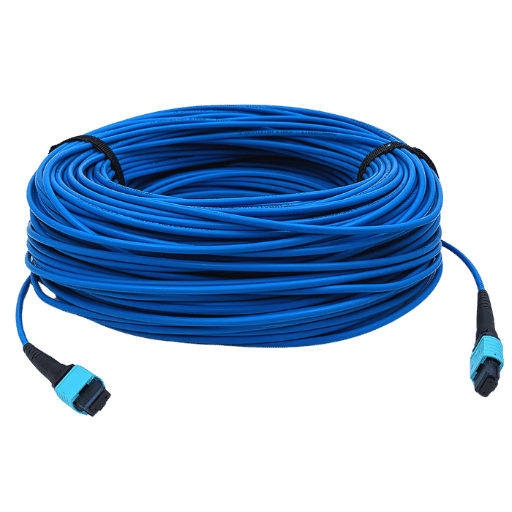
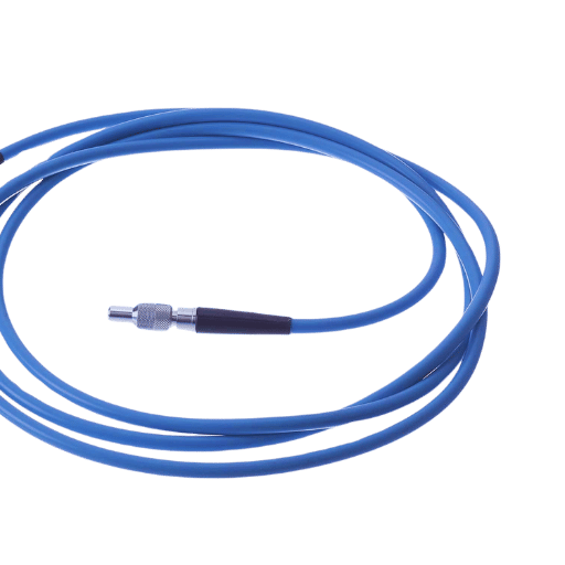
Biased from the above context, blue fiber cables are being defined as the cables which have a blue color jacket and come into the category of MMF. It means such cables are able to transmit within a core several light signals since they are made to support many modes of light. The standardized color coding helps to identify and appropriately arrange the cable infrastructural networks that are intricate in nature. dominantly blue fiber is used in data centers to, local area networks, LANs, and interconnection that are on the shorter range. Expansion of available bandwidth is achieved with blue fiber cables while optimally reducing the development and maintenance costs.
The hierarchy of fiber optic cables is twofold: single mode and multi-mode which cater for varying geometric reach as well as bandwidth capacity.
In the end, the selection between single mode and multi mode fiber cables depends on the extent, data rate, and budget of the particular telecommunications project in order to obtain high performance, low cost fiber networks in different telecommunications and data handling tasks.
Blue fiber is sometimes used to rename the types of optical fiber cables employed for specific network uses, such as the ones employed in the telecommunications sectors. Even in the absence of defined industries and standardized uses, blue-jacketed fibers are generally used in data centers for high-density interconnectivity where a clear physical layer interconnection is necessary. These fibers meet the needs of data transfer in organizational contexts and play an important role in the network and cable organization and management systems. They further enhance the appearance of the structure by making patently clear the spaces employed in blue fiber, which is very effective in communication network operations where slight color differences are used to boost the performance of overall monitoring systems.
Cables made of fiber optic have several critical telling advantages over copper cables, such that they have found the technology to communicate much faster,” Kowalski states. To begin with, the amount of bandwidth they are capable of transmitting is multiple times greater, with the upper limit being several terabits in the range. Such an assurance is important in light of the explosive growth in demand for data intensive uses such as: video on demand, cloud data services and electronic bulk data communications, Furthermore, all of the above are supported. Fiber optic cables have significantly lower attenuation and allow increased distances to be achieved in signaling without the need for amplification, which means that the cost of deployment and infrastructure increases and the efficiency of the network as a whole is increased.
Apart from that, the resistance of fiber optic cables to external electromagnetic interference makes fiber optic connections more stable while maintaining the quality of the data transmitted. This factor is particularly relevant for industries and cities where electromagnetic interference has a negative impact on the operation of communication devices. In addition, with such advantages, the lightweight and small diameter make installation and maintenance less difficult for even hostile physical conditions. As projected in the recent industry surveys, the worldwide fiber optics market from 2023 to 2030 is expected to have a CAGR of 8.5 percent which indicates the growing dependence on fiber optics to boost the network’s performance and state-of-the-art technology.
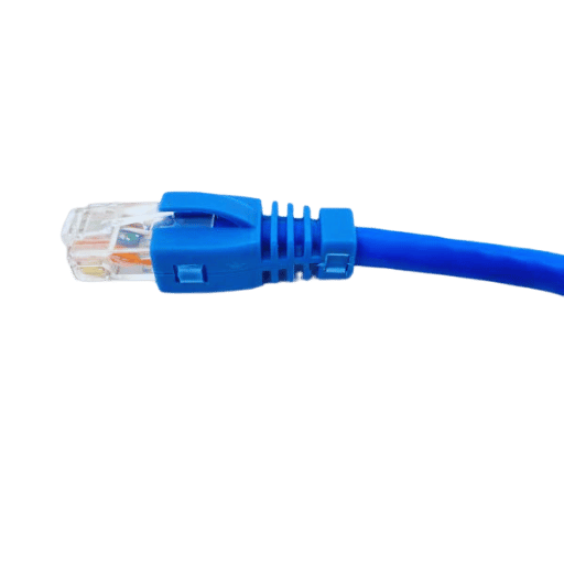
The main difference between multimode and singlemode fiber is in the core size of each fiber type and also the way light is transmitted through them. Below are data points and features that explain the differences between the two:
Core Diameter:
Light Source:
Transmission Distance:
Bandwidth:
Applications:
Such knowledge also fosters understanding between the network engineers and planners in determining the appropriate type of available fiber optic cable for specific purposes for the most effective and economical deployment of the network infrastructure.
OM3 and OM4 are the Types of Optical Fiber Multimode Ferrules designed for use in data centers and high-speed LANs with different data transmission and distance features. An OM3 fiber is designed and built for a maximum distance of 300 meters and a capacity of 10 Gb/s transmissions. OM4, on the other hand, also accommodates 10 Gb/s but increases the length to as far as 550 meters. Additionally, it can provide 40 Gb/s and 100 Gb/s over shorter distances. The main difference between them is their bandwidth, as a modal bandwidth of 2000 MHzkm was recorded for OM3, while OM4 was found to have an increased bandwidth of 4700 MHzkm. Such improvements in the construction of OM4 fibers can provide higher-grade flexibility and efficiency of the network’s installations and cover the rising cable length and data transmission rate constraints.
In multimode fiber optic networks, the LC connectors have a significant impact thanks to their small form factor and high performance level. These connectors use a 1.25 mm ferrule, which is one-half the size of the SC connectors, making them suitable for tightly packed data center areas. Their excellent return loss and insertion loss enable high data rates to be transmitted with little or no degradation of the signals. As the last industry development news has shown, LC connectors are largely used in areas requiring compact connections, which in turn support OM3 and OM4 fibers to operate with larger bandwidths. For example, they enable the transmission via 10 Gb/s, 40 Gb/s, and even 100 Gb/s connections, which are required in today’s databases. The push-pull mechanism gives a locking arrangement to the connector and minimizes the risks of network downtimes, and lower maintenance costs. Moreover, their deployment in network advancement of 400 G and beyond indicates how important they are in the development of multimode fiber.
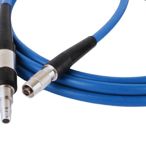
Factors that are critical in making a decision regarding LC to LC connectors include the required data rate and distance, which help in deciding whether to choose either OM3 or OM4 fiber types. Assessing the space limitations of the environment is important in order to take advantage of the compact structure of LC connectors. Make sure the equipment will fit in the current hardware and any developments in the hardware that may end up requiring 400 Gb/s. Finally, ensure that the quality of the connectors will be sufficient to meet the needed insertion and return loss metrics for the integrity of the signal to be maintained and save on maintenance expenditure for the network.
In order to establish whether simplex or duplex fiber would suit your networking needs best, you should first know how each type is specifically used in networking. Simply put, duplex fiber consists of a pair of fibers encased within a single sheath which allows for bi-directional communication to occur simultaneously. This configuration is useful for telecommunications and data center applications where bi-directional communication is a must. Simplex fiber, on the other hand, consists of a lone fiber designed to operate in one direction only, thus making it applicable in any situation where return communication isn’t required, such as in some industrial areas.
From a transmission point of view, duplex fibers are able to transmit a higher volume of fiber data as transmission streams more than one data concurrently, which is more desirable in high bandwidth applications. For example, there are LC duplex connectors in use today to cater to the demand for so much data in most of the data centers. Industry figures indicate that duplex configurations can achieve 25 Gbps per channel, or as much as 100Gb/s, through the use of parallel channels. Conversely, simplex fibers may be used for basic networks where the overall system is cost-sensitive due to the fewer wiring materials used and smaller cable sizes offered.
In the end, it is the network requirements, cost aspects, and future expansion of the system that should determine whether simplex or duplex fiber is used. Having such considerations in mind makes it possible for organizations to utilize effective and reliable data transmission that fits their operational needs.
Outer jacked fiber optic cables serve an important function and must also assist in the protection of the cable. Not only does the jacket protect the inner fibers from the damaging effects of moisture and ultraviolet ions, but it also provides mechanical protection from suffering physical stresses. It is critical to ensure that the jacket material selected meets the expected performance requirements and reliability of the fiber optic infrastructure. Given below are the commonly used outer jacket materials with specific characteristics:
Polyvinyl Chloride (PVC):
Low Smoke Zero Halogen (LSZH):
Polyethylene (PE):
Thermoplastic Elastomer (TPE):
Polyurethane (PU):
The installation environment and regulatory requirements are exposures to hazards that should be taken into account when selecting the right outer sheath composition. Such an approach increases the efficiency of optic fiber cables and their protection mechanisms.
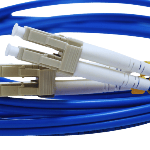
Different kinds of specialized tools on the field or in the workshop will be required in electronic and fiber optic splice transfers, some of which include the following:
Installation of spliced optical fibers requires the use of these tools to ensure that the splices are of high standard, strong, and resistant to any external forces.
In the following sections, we discuss ideal locations for common construction defects, including butt joints and splices. Taking into consideration both appearance and optimal practice, it is important to note that these problems do not discharge the juxtaposing construction merit – only their quality is substandard and has been compromised.
Purchasing from Cables.com is meritorious in terms of quality assurance and customer satisfaction. First of all, Cables.com has a large variety of LC fiber optic products which enables meeting different technical specifications and various network topologies. Second, the company maintains strict quality control which is supported with relevant certificates verifying compliance with high industry standards. In addition, Cables.com guarantees reliability through its focus on superior customer service, which encompasses adequate technical assistance and fast answer to any questions. Finally, the company’s logistical operations are well organized in order to enable timely delivery in line with tight time schedules and hence improve the overall performance of the projects.
A: An aqua blue fiber optic cable is one of the most distinctive colored multi-mode optoelectronic cables used in welding high-speed Ethernet subnetworks, for it is specifically coded for these purposes.
A: An example is multimode fiber optic cables such as the blue fiber optic jackets which are intended to cover lens arrays within particular multimode connectors which would be ideal for short distance transmission but would be less ideal for longer distances since it would be relying on single mode fibers for coverage.
A: A visual fault locator is a low-cost electronic instrument which contains a laser that can easily penetrate deeper inside the tough coat of fiber cables and can detect procedures and components that are malfunctioning within a range of thirty centimeters.
A: Yes, multimode fiber cables support the duplex multimode round cabling plan allows the use of two fiber cables the same applies for 10gb Ethernet systems with allows sustenance across a reasonable travel distance.
A: Cables such as LC fiber patch cables are used to connect patch panels, ethernet switches, and media converters through fiber optic patch applications.
A: The aqua blue color, for example, is known to be the jacket of the 10 Gig OM3, which is used in telecommunication systems color coding as well as management of the cable in use within fiber patch pulls.
A: If you want to make sure that the cables you ordered will be shipped on the same day you ordered them, make sure to get the suppliers who have the needed cables in stock, like custom cables or cat6 and cat5e suppliers.
A: OS2 is a single-mode fiber optic cable with a large fiber core and cladding designed for use over longer distances, as opposed to a multimode fiber optic cable, which has a larger fiber core.
A: Multimode fiber jumpers refer to the various cords used to link different devices, such as patch cords or jumper cords. These cords are relatively interchangeable in length, with the common measurement being 3 meters.