With the growth of the field of fiber optic technology, it is apparent that mechanical splicing is a core process that provides joint organization and data flow. This procedure is essential in telecommunication and data communication systems, making it helpful in connecting optical outputs. For instance, in fusion splicing, to join two ends, one has to melt the fibers, whereas, in the mechanical approach, the ends are joined with the help of mounts and liquid refracting at the gap. This introduction aims to put in perspective the essence of the presently multifaceted term mechanical splicing, including its fundamental principles, and place it into a broader context of fiber optic technology. The considerations structured this way will enable the readers to comprehend how these processes and tools of mechanical splicing enhance the operational performance of current fiber optic networks.
What is a Mechanical Splice?
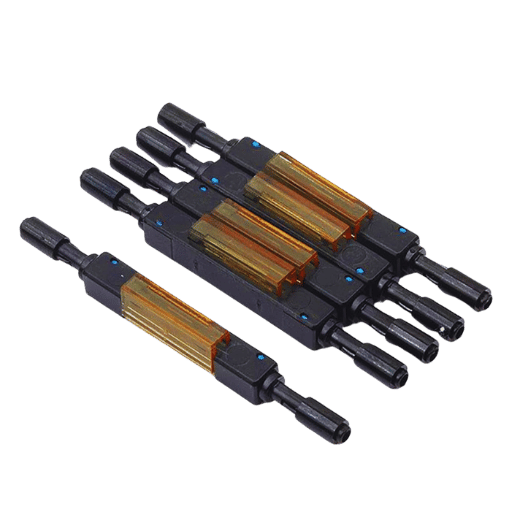
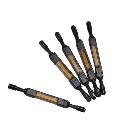
A mechanical splice connects optical fibers used in fiber optics to transfer signals and light together in an end-to-end manner known as an end-to-end optical fiber connection. It employs a mechanical device to hold and align the ends of the fibers. It uses index-matching gel at the joint to minimize both reflection and insertion losses to increase the fiber joint’s resistance. In mechanical splicing, there is no use of heat or melting of the fibers, which makes the repair quick. It is effective in temporary or emergency repairs where no fusion splicing equipment exists. Since mechanical splicing is easy and cheap, it has been widely used in other areas requiring fast and effective fiber restoration.
Understanding Mechanical Splice
In a mechanical splice, the main function is to bring together the ends of the stripped optical fibers in a holding device. The procedure typically involves cleaning and cleaving the fibers, placing them in a holder, and locking them. This means there is a reduction in the reflection and loss of light at the joint region. Due to this, signals are successfully transmitted through fiber optic cables. This technique has advantages such as cost-effectiveness, operator-friendliness, and speedy splice provision as such opportunities arise. This technique may have drawbacks since it may not be as permanent or strong as the fusion splicing technique; hence, it is more applicable in temporary and test applications.
Difference Between Mechanical Splice and Fusion Splice
Mechanical splicing and fusion splicing are both used to join two pieces of optical fibers, but these processes and their practical importance are very diverse. Mechanical splicing requires the internal ends of the fiber strands to be aligned inside a mechanical apparatus, and the end surfaces are treated with an index-matching adhesive to reduce optical loss. Due to its effectiveness, the bottom-up assembly method is used, especially where rapid action is required, such as in temporary repairs, since it is fast and cheap.
On the other hand, fusion splicing facilitates the permanent connection of fibers by simply fusing the ends of the fibers through the electrical arc. This method provides a timesaving way of making connections since it provides a tighter and more secure joint than any other method with low transmission and reflection losses. However, it requires certain instruments and is normally quite costly and lengthy when compared to the former. Because of the strength of fused joints and signal quality, including most of the long-distance and other stationary fiber optics applications, fusion splicing is used when high performance and reliability are needed.
Applications of Mechanical Splices in Fiber Optics
As they are non-complex and inexpensive, mechanical splices are rather popular amongst the users of fiber optics. In specific fields, these splices enable temporary emergency repairs, where timeliness is of the essence. They allow for quick restoration of broken fiber optic links without the use of any tools and form a handy resource in the fields and other temporary repairs. In addition, many testing designs and frameworks use mechanical splices as they allow for changes and reconfiguration of the structure and elements without making firm connections. Their feature will enable them to be used in cases where the configuration often needs to be changed, like in R&D or demonstration setups.
How to Perform a Mechanical Splice?
Tools Needed for Mechanical Splicing
In the course of carrying out a mechanical splice, there are some critical tools and materials that are needed to enhance efficiency. The first is a fiber optic cleaver which is important as it facilitates some accurate cuts on the fiber in order to produce a flat surface that helps in the interconnection. An optical fiber stripper is also used, but this time for stripping of fiber coatings or jackets without damaging the fiber. For splicing purposes, fiber alignment fixtures or holders are required to support and orient the optical fibers in such a way that the intended splice is physically maintained. Adhesive or index matching gel may also be needed for better butt or m-force connection between the ends of the fiber optic, ensuring that the fiber optic connector fulfills its objective of reducing the loss. Last but not least, a visual fault locator is also quite helpful as it helps to check the alignment and continuity of the fiber after splicing by passing a visible laser light through the fiber that has been spliced. These particular tools enable the effective carrying out of a mechanical splice by making sure that the appropriate preparation and alignment of the fibers is done to achieve a perfect join.
Step-by-Step Guide to Mechanical Splicing
Prepare the Fiber Ends
With the optical fiber stripper, proceed to remove the outer coatings of the fiber, but try to avoid nicking or damaging the fiber itself.
Cleave the Fiber
With the aid of the fiber optic cleaver, make an even perpendicular cut on the fiber. This is also very important when making a fiber splice. Therefore, the end face should be not only flat but also smooth.
Align the Fibers
Insert the cleaved fibers into the fiber alignment fixtures or holders, aligning them in a clean cut and accurate orientation to lower the insertion loss.
Apply Adhesive or Gel
When necessary, the last step is done by covering the fiber ends with adhesive or index matching gel in order to create the best possible connection and eliminate the reflection losses.
Join the Fibers
When parallel with the other fiber, the applied tips must lead the fiber ends in contact with themselves through the mechanical splice enclosure, fixing the fiber ends according to the splicing instructions provided by the manufacturers.
Verify Alignment and Continuity of the Splice
After completing the previous drawing, a visual fault locator generates light energy with a relatively high power. This finished incorporating the alignment and continuity checking steps, which entails looking for leakage or disturbance of the light signal.
Tighten the fiber splice, ensuring that physical contact is maintained between the fiber ends within the splice holding fixture for maximum efficiency.
When the splice is complete and if the conditions are verified, a clear casing will be put over the joined fibers to ensure they are properly secured and prevent any movement due to strain.
Common Mistakes to Avoid in Mechanical Splicing
Inadequate Cleanness
Neglecting to clean the fiber ends might affect the light transmission and increase signal degradation. Make every effort to clean the fibers thoroughly before you perform a splice.
Improper Cleaving
Fibers with poor or slanted ends, caused by either poor cleaving or skiving of the protective tube, are less likely to fit, which could rather cause significant insertion loss. Make sure no cleave is perpendicular and that there are no sharp cuts.
Bow of Fibers
Even the slightest deviation can result in loss of optical performance. Proper alignment devices should be used to avoid any misalignment during the splice.
Over: Glue or Gel Use
If you apply too much overuse, it can lead to soiling or excessive attenuation. Only the appropriate quantity of maximum efficiency is applied.
Avoiding Continuity Tests
Neglecting to check the continuity of the fiber and continuity of the signals may result in undetected system faults and, later, system failure. When using a visual fault locator, always check.
Improper Closure of Splice
Not fixing the sheath properly may make the splice break or get off its bias when a load is placed on it. Comply with the tightening recipes and floppy splices all the time.
Advantages and Disadvantages of Mechanical Splices
Benefits of Using Mechanical Splices
Mechanical splices possess a few critical factors regarding fiber optic applications. They allow a rapid, affordable method of fiber jointing that is particularly beneficial in the field where time and costs are limited. The technique is easy to learn and does not require advanced technology or tools. Also, mechanical splices facilitate redesigning or maintaining fiber networks without heavy tools and cumbersome procedures. This also allows for standardization of performance over connections, assuring low insertion losses and, therefore, reliable data transmission when done well. It can be keenly deduced that mechanical splicing is preferred where there is a need to maximize efficiency, keep costs reasonable, and enhance ease of use.
Drawbacks of Mechanical Splicing
Despite the fact that mechanical splices are useful and economically viable, they have some limitations, too. One major limitation is increased insertion loss, in some cases, such is the case of most active technical devices when interfacing with optical fibers, optical performance may not be up to the mark. This is partly because, at the insertion point, fibers are not very well aligned. In like manner, mechanical splices may not have adequate strength, be insensitive, and perform well under temperature or humidity and moisture exposure, heat, extreme pressures and shocks, and extreme use. When adhesive or gel is employed, these splices may provide ease; however, over time, the substance is bound to degrade, which promises further costs on maintenance or revision, making the operation cost even more. With appropriate evident parameters, mechanical tension should preferably not exceed the maximum load rating. While effective short-term solutions to certain problems, mechanical splices are not always appropriate for permanent operation on systems requiring high standards.
Comparison with Other Splicing Methods
Two common types of fiber optic connectivity are closely associated with the above: mechanical splicing and fusion splicing. This is because of the lower insertion loss obtained from the accurate fusion of the ends of the fiber. High-bandwidth systems tend to exhibit superior performance in this method. This method of fusion splicing requires more elaborate equipment and training of the technicians, which may drive up the initial costs. Mechanical splicing, on the other hand, is economical and more suited for applications requiring rapid deployment and configuration, particularly the installation of fiber optic cables. To this day, mechanical splices are of great use in most base station and emergency applications despite their common construction and the fact that they are exposed to the environment and have higher insertion loss. Ultimately, when allowed to select among the alternatives, the ultimate considerations include performance needs, limited monetary resources, and the surrounding environment.
Types of Mechanical Splices
Overview of Different Mechanical Splice Types
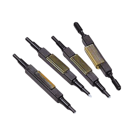
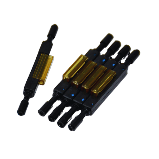
Mechanical splices consist of essential types which are employed depending on the needs of the project. Elastomeric Splices, such as those that consist of an elastomeric element, provide quick and flexible connections through the alignment and holding of the two-fiber ends. Capillary Tube Splices use a thin glass or metal tube that aids in holding the two fibers, with the ends often submerged in an index-matching gel to reduce reflection and loss of light. V-Groove Splices are simple techniques where the two fibers are held by inserting them into modified plastic or ceramic tubes having well-defined grooves. This type of splice is mostly attractive due to its low cost and simplicity in design and handling. Each type is catered to perform a variable function concerning the speed and precision of the fiber alignment.
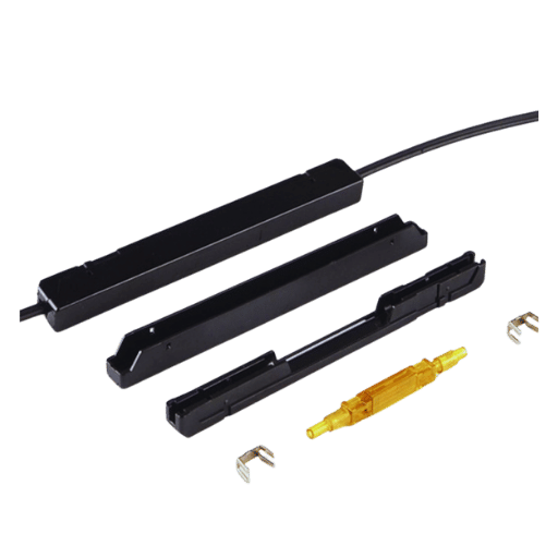
Characteristics of SpliceConnect Mechanical Splice
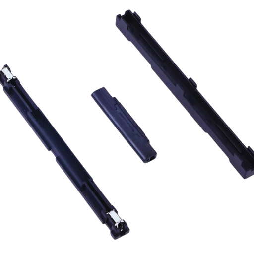
SpliceConnect is an easy-to-use mechanical splice kit for quality optical fiber termination. Performance characteristics include easy installation as good as fusion splicing that achieves 0.2 dB typical insertion loss, suggesting good quality usable for a range of applications requiring fiber optical mechanical splices. Such apparatus also integrates some index-matching gel-aided components in place of splicing devices to correct losses but permits using different types of fibers in single mode and multi-mode. The design goal of SpliceConnect is to be installed in a user-friendly manner, usually using minimal tools and training while maintaining high operational effectiveness and low costs. Besides this, such a device is further supported by effective sealing means appropriate for indoor and outdoor use.
Single Mode vs. Multimode Mechanical Splices
Single-mode and multimode mechanical splices differ only in their usage and the type of fibers they are designed for, constituting the performance of the fiber splice. Single-mode fibers have smaller core diameters, and as such, light travels through a single path along the axial of the fiber, therefore minimizing dispersion and maximizing distance separation in communication. On the other hand, monomode fiber has a high Core to cladding portion. This Core can support multiple light modes but is ideal within the short range for high bandwidths within a local area network. Single-mode fibers, while having reduced orientation tolerance of the splicing interface insertion loss, are often more demanding for precision micro attachment and fiber core alignment than attempts with multimode fused splicing, which has a more forgiving core geometry. The choice between the two types rests on the network specifications regarding distance, bandwidth, and price.
Maintaining and Testing Mechanical Splices
Inspection and Maintenance Tips
Mechanical splices must be properly checked and maintained to promote an acceptable performance of the fiber optic network. First, the connectors must be routinely cleaned, and the splice joints must be examined with the fiber optic inspection scope for swabbing or alignment. This examination enhances the detection of impurities or imperfections that can harm signal quality. Moreover, the protective cover of the splice must be fitted appropriately and locked against rain or other environmental elements. It is also essential to resolve this by having the optical time-domain reflectometer (OTDR) employed periodically to measure Splice Insertion Loss (SIL) and reflection content to check if the Splice is within the performance requirements. These practices help reduce fatigue and help preserve the quality of the fiber optic network.
Testing Mechanical Splice Integrity
The verification process of mechanical splices includes using special tools and techniques to evaluate and assess the quality of the connection. An optical time-domain reflectometer is the main instrument for testing the integrity of mechanical splices. The delimiting device evaluates the splice’s insertion loss and its overall reflectance to determine certain qualitative traits that may include splice failure. Even in this case, testing is done under controlled parameters where outside conditions do not interfere with the outcome. Consistent testing schedules prevent such problems from occurring as network operators determine any gaining or deteriorating aspects and resolve them effectively, hence ensuring the integrity and efficiency of the fiber optic network.
Dealing with Mechanical Splice Failures
The first step in solving the problem of mechanical splice failures is to examine how a particular failure has occurred carefully. Some common problems with splices include the presence of misalignment, contamination, or malfunctioning hardware. Once this has been done, appliances will remove any contaminants or dirt from the splice components and carry out an alignment verification procedure. Functional defects should be fixed, and the splice should be put back together with particular attention paid to the outer case, which must keep the fiber and the coating intact and away from the elements. In addition, following reassembling, a performance test of the splice should be done using an optical time domain reflectometer (OTDR) to show compliance with performance requirements. The use of planned surveillance and maintenance activities and adherence to established engineering methods will help protect against future failures and ensure a high level of operational reliability for fiber optic mechanical splice joints.
Reference Sources
Optical fiber
Mechanical splice
Glass
Frequently Asked Questions (FAQs)
Q: What do you mean by mechanical splice in fiber optics?
A: Mechanical splicing involves joining two or more pieces of optical fiber without heat. It employs a small tool that pinches the ends of both clean fiber ends in an appropriate position; often, index matching gel is added to reduce the amount of light lost when the two fibers touch. Mechanical splices are a relatively cheap and fast way of connecting fibers, which makes them suitable for a temporary or emergency solution in the case of repairing a fiber optic network.
Q: Where is index-matching gel utilized in the mechanical splices?
A: The use of index-matching gel is essential in mechanical splicing. The refractive index of this gel is closely related to the fiber core. Due to this, the Fresnel reflections created on the two interfacing fibers are suppressed. This gel prevents rough ways of interface since it fills the space between the two fiber ends without any air, thereby reducing the insertion loss and enhancing the quality of the splice.
Q: What are the steps involved in creating a mechanical splice?
A: The general course of action includes: 1) Fiber coating strip using fiber stripper, 2) Precision fiber cleaving of bare fiber, 3) Cleaning of fiber ends, 4) Insertion of fiber into mechanical splice apparatus (usually has v-groove for mucilage alignment), 5) Fixing the inserted fibers in place, and 6) In event that index matching gel has not been loaded into the splice, putting it around the intended index.
Q: How does a mechanical splice compare to a fusion splice?
A: Even though fusion connections have the advantage of lower loss and more permanent union, liner groove substitutes have merits. They take less time to fix, do not need costly thermoplastic gizmos, and can be readily redone if necessary. However, it is worth noting that the mechanical configurations normally have a high comparative insertion loss of around 0.2-0.5 dB against 0.1dB less for the adaptive fusion clips.
Q: Are mechanical splices compatible with answers of both single-mode and multimode applications?
A: Yes. Mechanical splices can be applied to both single-mode and multi-mode fibers. However, the right splice for the particular fiber due to its core size and core alignment differentials is essential. A few products on mechanical splices can be used for both modes; however, some can be designed only for single-mode or multi-mode.
Q: What is SpliceConnect by AFL, and how does it work?
A: Stress applied by the user and surrounding construction elements is relieved during the final steps of energizing the SpliceConnect, the rigid mechanical splice with optical fibers. It locks the optical fiber and its coating alone to ensure the correct arrangement and effective stress relief. This type of mechanical splice allows the splice fibers to remain in contact, and the index matching gel is also used, which helps in reducing attenuation. Thus, it can be used for different types of applications in a fiber network.
Q: What steps would you follow to prepare a bare fiber for use in a mechanical splice?
A: Preparing bare fiber for a mechanical splice involves several steps. First, a fiber stripper is used to peel off the outer coating, exposing the cladding. Second, the stripped fiber is washed with alcohol to clear remaining dirt. Third, a fiber cleaver of good grade is used to develop a neat perpendicular end. Fourth, the cleaved face is visually observed for any abnormalities. Low splice losses require proper monitoring by ensuring the two fibers in contact are prepared correctly.
Q: How much is the typical splice loss for mechanical splices?
A: Mechanical splices, on the other hand, are known to exhibit higher splice loss than the fusion types, and this can be a crucial determinant in the choice of fiber optic connectors. The mechanical splicing techniques can amount to splice losses of 0.2 to 0.5dB. However, high-end products may bring the splice losses down to 0.1 dB. Many factors influence interpolation loss, these include, fiber cores alignment quality, end faces of the fiber cores and index matching gel application techniques.
Post Views: 5,026


