A fiber optic cable locator is an integral part of deploying, maintaining, and troubleshooting fiber optic networks. However, the emphasis on accurate and controlled testing equipment increases as the data transmission rate increases. This paper examines the depth of the techniques used by visual fault locator meters to locate specific faults, including any breaks or bends in fiber optic cables. With knowledge of the features and usage of these devices, technicians can perform proper testing management, leading to the best network performance.
What is a Fiber Optic Cable Locator?
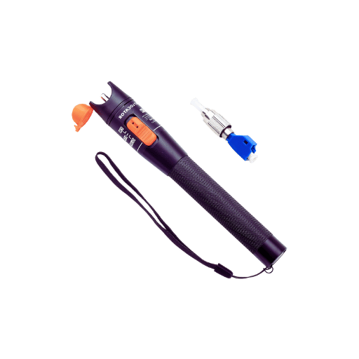
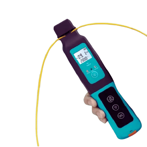
A fiber optic cable locator is one of the tools used to detect and pinpoint malfunction occurring in the fiber optical cables. In normal practice, such devices use a red-colored light, fittingly known as functional light, to signal through the fiber so that the technician can visualize breaks, kinks, and other abnormalities that disrupt the passage of the beam. Fiber optic cable locators quickly and exactly find the faulted region of the fiber where the signal is incomplete, and that is why they are important in the improvement and upkeeping of fiber optic network electrical or signal activity interruption.
Understanding Fiber Optics and Visual Fault Locators
Among these types of structures, fiber optics are the thin strands of silica or polymer that transfer information in light pulses. Fiber optic data transmission cables are flexible composites of many fibers that facilitate turbo data transfer over considerable extensions with little attenuation. Visual Fault Locators (VFLs) are primarily employed to inspect and maintain these Fibre Optical cable systems. VFLs deliver visible laser brighter red through the fiber’s core, which penetrates through and causes gross flaws such as cutouts and other light emissions. The immediate perception reduces the time taken to locate and rectify abnormalities in the system, ensuring that communication remains efficient and effective.
Key Components and Features of a Fiber Optic Cable Locator
- Laser Source: This focuses a bright red light to find damage in the optical fiber.
- Connector Interface: This makes using different fiber optic cable classes easy.
- Power Supply: It is either by way of a dry battery or it can be charged.
- Wavelength Specifications: Generally, 635-650nm is the megahertz range that tends to be scorchingly bright.
- Output Power: This determines how effective the fault illumination will be, usually in milli Watts (mW).
- Durability: It comes with a sturdy housing that protects it from usage in the field.
- Portability: The structure and weight are designed not to cause discomfort when used anywhere.
- Safety Features: This includes using certain safety measures to avoid the risk of accidentally pointing the laser beam.
The Mechanism Behind a Visual Fault Locator
The VFL works by projecting a red visible laser light beam through the fiber optic cable. This light is usually visible and used to locate any breaks or bends in the fiber optic cable. When the fiber is broken, the light comes out from that area because of the exposure of the internal section of the fiber to the air. This allows technicians to see where the problem is in the cable and fix it quickly and efficiently, ensuring the buildings on-net are dependable. This procedure ensures that the fiber network operates effectively and reliably.
Why Use a Visual Fault Locator for Fiber Testing?
The Interactive Fiberscope – Common Issues Detected With Visual Fault Locators
- Fiber breaks: The realistic and unbounded unity in the fiber causes the break in the signal.
- Bends: Overstretching of fiber from a single cable causing loss of the signal or attenuation.
- Connector Faults: Faults in the alignment and physical damage of the connectors.
- Splice Failures: Signal drop out due to poor or non-splicing out of several fibers from a cable.
- Microbeads and macro bends are bends occurring either on a very small or large scale that adversely affects the optical signal.
- Mechanical Damages: Any external stresses acting on the fiber causing damage to the fiber.
Benefits of Using a Visual Fault Locator
- Efficiency: Identifies with precision the exact location of the faults, leading to improved problem-solving speed.
- Cost-Effectiveness: It reduces idle time and repair costs by quickly resolving problems.
- Versatility: It has many applications, including detecting fiber breaks, bends, and connector faults.
- User-Friendly: The fault-locating procedure is not complicated, so both novice and experienced technicians can perform it.
- It improved Network Reliability. Every time any breakage is detected in the fiber destined for fiber-tracing, it can be corrected quite rapidly which aids in optimizing the networks.
Impact on Network Infrastructure Maintenance
- Fault Detection Speed: Greatly shortens the time needed to identify and find faults.
- Maintenance Costs: Reduces total maintenance costs by reducing repair time and downtime.
- Network Reliability: Provides increased network dependability through faster resolution of faults.
- Technician Efficiency: Increases the technician’s efficiency by easing the processes of distilling sources of problems.
- Service Continuity: Helps in the continuous operation of the network through effective and timely maintenance support.
How to Use a Visual Fault Locator For Testing?
Safety Tips and Best Practices
- Always Wear Protective Eyewear: Protect the eyes from intense laser radiation or reflected laser light.
- Inspect Equipment Regularly: The VFL and all its related accessories must be checked for appearance and performance.
- Follow Manufacturer Guidelines: Follow the equipment operation procedures and all safety rules given by the manufacturer.
- Avoid Direct Eye Exposure: Avoid looking into the VFL’s laser beam.
- Disconnect Fiber from Active Systems: Turn off any active network that is linked to the fiber before beginning any physical evaluation.
- Store Properly: When not in use, a device should be returned to a clean and dry environment to lengthen its working life.
- Use Correct Output Levels: The VFL output should be set to a level appropriate for the application so that no hardware is damaged.
Explaining the Results
When carrying out a fault analysis with the help of a Visual Fault Locator (VFL), clearly defined steps are followed while interpreting results from fiber tracing to avoid misdiagnosing or undergoing the wrong repair.
- Visible Light Indication: When the VFL is put on; a bright red laser light appears at the outer surface of the fiber and runs through the length of the fiber. Any amount of light appearing somewhere indicates the place of the fault.
- Light Leakage Points: Record cases when the laser intersects the fiber and escapes outside the fiber. They indicate the areas of severed, bent fibers and bad ejectors.
- The intensity of the Light: Seek the brightness of the light. Bright light and a beam that does not flicker mean a good connection. A beam that is dim or comes in fits means there is a partial fault or a point of high loss.
- End-to-End Continuity: In this case, it is prudent to check if light passes through the whole length of the fiber from the two ends. If light is shown at one end of the fiber, light emerges from the other end, and the entire or parts of light travel through the fiber, then most probably, the fiber is free from faults.
Properly examining these indicators allows efficient diagnosis and troubleshooting for systems engineers in fiber optic networks, aiding in proper repairs and preventing unnecessary outages.
Product Description and Technical Details
Features To Consider When Buying A Visual Fault Locator
- Laser Wavelength: The VFL should preferably be designed to work at a uniform and standard wavelength of about 650 nm, as this ensures high visibility and compatibility with most fibers.
- Output Power: Many products, such as a visual fault locator, have flexible multi-level output power from the lowest to the very highest.
- Battery Life: A good VFL should have a long battery or a rechargeable battery that can be used for several hours continuously.
- Connector Compatibility: Ensure the VFL has a standard or converting interfaces for different optical fiber connectors such as SC, FC, ST, etc.
- Mode Options: Choose a VFL that provides channels in continuous wave (CW) or pulsed mode for varied test applications.
- Durability: Aim for a hard and tough VFL, preferably with a cover to protect it from adverse field conditions.
- Visibility Range: Investigate the device’s visibility range, ensuring that the automatically detected faults can be in fibers several kilometers in sight.
Technical Specifications
- Laser Wavelength: 650 nm
- Output Power: 1 mW to 10 mW adjustable range
- Battery Life: 8 hours of continuous operation maximum
- Connector Compatibility: SC, FC, ST compatible
- Mode Options: Continuous wave (CW) / pulse modes
- Durability: Casing withstands impact
- Visibility Range: Maximum to about 5 km
Understanding the Measurement Units
Measurement units used in visual fault locators (VFLs) are essential and must be factored in when considering the performance or integration of fiber optics systems. Here are the fundamental ones focused on:
- Laser wavelength (nm): The wavelengths of the emitted laser are measured in nanometers, which in the case of VFLs tend to be 650nm to allow visibility and comply with basic fiber optics.
- Output Power (mW): The strength of the laser’s output in milliwatts is quantified in mW. There are adjustable settings between 1mW and 10mW, normally adjusting from 1mW to 10mW, allowing for specific fault locations on varying lengths and types of fibers.
- Battery Life (hours): This is measured in hours, and it indicates how long a VFL can function uninterrupted on a single charge. The units are preferred in the field since they help eliminate low operational power.
- Visibility Range (km): Kilo meters (km) measure the effective distance at which the VFL can locate a fault. Operatively, the up to 5 km range is sufficient for most situations.
Grasping these units permits the choice of an appropriate VFL suitable for specific testing and field requirements, thereby guaranteeing efficient and accurate fault identification on fiber optic networks.
Customer Reviews and Recommendations
Customer Feedback on Performance and Reliability
- Durability: The shockproof housing ensures the product lasts longer than expected, and most customers even mention it being durable during field work.
- Battery Life: Most users have reported of a long battery life which enables them to use the device throughout their work without the need to re-charge it.
- Visibility Range: A maximum visibility range of 5 km is sufficient to cover a number of fiber optic systems promoting different utilizations.
Overall, customer feedback supports the assertion that the VFL is a reliable device that resolves the professional in-parts requirements of “Testing of fiber optic cable systems.”
Feedback from the Field and Product Differences
Industry specialists have assessed our visual fault locators (VFLs) in great detail, validating customers’ positive comments. VFLs are well-rated in expert evaluations of devices for their accuracy, quality of construction, and ease of operation. Some key considerations mentioned by the specialists are:
- Effectiveness: The specialists say the VFLs are effective in fault detection even for variations in fiber configurations and fiber environments.
- Casing: The case is one of the positive comments concerning its rugged and shockproof exterior, which is important in the field.
- Batteries: One of the beneficial aspects of constructing an instrument that utilizes minimum energy is that specialists observe that in terms of battery life, one is less likely to take such devices for use on various projects.
- Freeness: A VFL is commended for its visibility, which reaches around 5 km, increasing the functionality of fiber optic networks’ deployment.
Despite these displacements, when we conduct head-to-head comparison tests, our VFLs are almost always placed in the first position compared to other models with regard to effectiveness, employability, and pricing. They recommend these VFLs for routine operations and also during fitting assistance for complex maintenance works in systems using optical fibers.
Applications of Visual Fault Locators in Varied Fields
Telecommunications and Data Centers
Visual fault locators (VFL) are an important part of fiber optics management and network repair. In these sectors, VFL is used to locate and fix breaks, bends, and other related problems when they affect performance to help reduce downtime. VFLs are also employed at the time of installation to check the condition of the new links while knowing how they are used. Data centers are also used to find faults at the core of densely populated physical infrastructures. This, as a result, means that any interruptions in service would be attended to in the least possible time, thus ensuring the efficiency of all activities. If there were any service problems in the operations of telecommunications and data centers, they would be put back in order quickly.
Cable Providers and Network Carriers
In addition to that, our objective is to apply Visual Fault Locators (VFLs) like the Orion Compact visual test set in cable providers and network carriers to enhance the functionality and performance of the fiber optic networks. VFLs have been used largely for trouble shooting and locating places of breaks, bends, or fibers poorly connected in the optical fibers. This makes it possible to quickly identify and correct any problems, thereby preventing prolonged delays and ensuring a good quality of service. While installing new network systems and repairing the old ones, VFLs also make running such networks at full capacity possible. That reduces downtime times and therefore increases customer satisfaction, making it necessary for cable providers and network vulgar to have VFLs.
Engineering and Infrastructure Projects
Visual Fault Locators (VFLs) are also useful in engineering and infrastructure projects. This helps to either install the faults or get rid of them for effectively putting up and maintaining the fiber optic cables. VFLs are becoming popular due to interference during installation and operation to discover and eliminate failure during installation. This level of accuracy helps to deliver a project on time, and more so when it comes to operating such essential services or infrastructure, the success and efficiency are maintained.
Reference Sources
Optical fiber
Database
Tool
Frequently Asked Questions (FAQs)
Q: What is a fiber optic cable locator and how does this equipment operate?
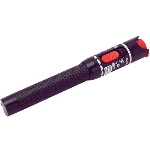
A: The fiber optic cable locator is pen-shaped and known as the visual fault locator. A VFL is used to look up and check the condition of fiber optic cables. It consists of a laser source that emits a bright red light that can penetrate the cable sheath and indicate to the service technician the place of fractures, bends, or other defects in the circuit of the fiber optic coil.
Q: What other features should customers consider when evaluating the brand and model of the fiber optic cable locator, as indicated in the product description?
A: In assessing a product description, scan through for some features for the wavelength (typically 650nm), output power (expect to find this within the 30mW range), range( usually up to 10km), connector type (2.5mm universal adapter design is often used), battery life, and any other support items such as a purse. These features recognize that the locator can be used in different modes of fiber optic testing.
Q: In what way does locating a fiber optic cable contribute to compiling on and near-net geographical lists?
A: A fiber optic cable locator can assist in producing the building list as it enables the technicians to follow the fiber directs and locate lit buildings, which is instrumental to telecom companies in globalizing and enhancing their networks. Telecom companies can take advantage of the fiber height and create a geographical map of currently covered buildings as well as look for near-net buildings for expansion.
Q: Do all types of optical fiber cables allow for locating devices?
A: Certainly, fiber optic cable locators are suitable for application in different types of fiber optic networks, such as telecom, data core, and local area networks. They are multifunctional devices applicable in the repair, maintenance, and installation of several fiber optic networks.
Q: In what way does FiberLocator provide added value regarding fiber search and fiber mapping?
A: FiberLocator ensures that customers have maps or even buildings with fiber or a lit system. This, integrated with a physical fiber optic cable locator, enables the technicians to search for the cable sufficiently well and make the fiber maps. Such a transfer of information between various units enhances performance in network asset logistics and planning.
Q: Why is Zeroing of a fiber optic cable locator device considered a portable feature that is well suited for fieldwork?
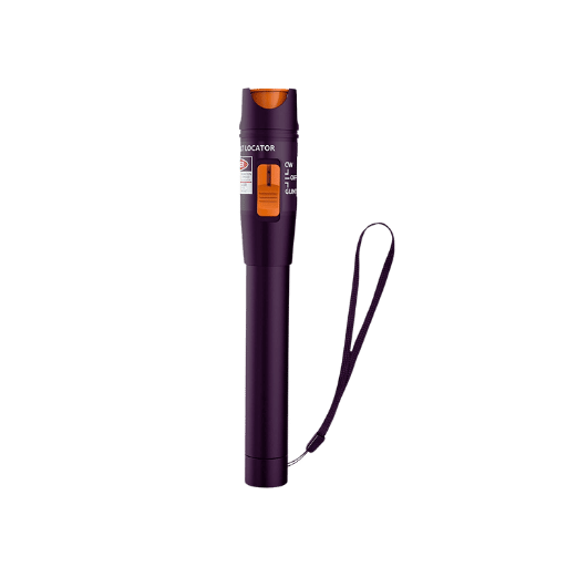
A: Most fiber optic cable locators are pocked-sized radiologists or pen-type structures, which considerably enhances portability. A number of such models have a suitcase, which is very convenient to put in a toolbox. These types of devices are small and light in weight, which makes it possible for technicians to conduct various field tests without having to carry bulky equipment.
Q: How do fiber optic cable locators assist in network coverage planning and deployment?
A: Fiber optic cable locators are very helpful in network coverage planning. They help technologists map existing fiber routes and, more importantly, determine the shortest routes for new connections. This information helps in making decisions on how best to optimize network coverage, identify new areas that need expansion, and determine which on-net and near-net buildings can be serviced.
Q: What should I know before buying a fiber optic cable locator on Amazon.com?
A: When buying a fiber optic cable locator on Amazon.com, consider factors such as the manufacturer’s reputation, product reviews, product specifications (output power, range, etc.), and the ASIN (Payment standard identification number) to avoid buying the wrong product. Search for fiber optic cable locators with universal 2.5mm connectors and hose attachments and those that come with pouches for carrying as a bonus.
Q: How can fiber optic cable locators help troubleshoot wiring issues?
A: Fiber optic cable locators have significant advantages when dealing with wiring problems in fiber optic networks. They can locate faults like breaks and bends in the fiber by using a bright light. This relieves engineers from diagnosis and allows them to work efficiently on areas where problems have been localized without the use of sequential tests, thereby reducing troubleshooting.
Q: What makes a fiber optic cable locator applicable to specialists and general technicians?
A: Fiber optic cable locators do not require special training for users; therefore, suitability applies to specialists and general users. They are easy to use and often consist of a single switch, which turns the laser on regardless of whether he/ she’s gone through any experience to that effect. Nonetheless, their accuracy and functionality are adequate to make them necessary in the hands of fiber optic systems specialists.
Post Views: 5,165


