When Senior Network Engineer Chen Wei at a rising fintech company in Shenzhen received new 100G switches for their data center, the SR4 modules ordered by procurement turned out to be unsuitable for the 2 km DR site. The team had to urgently source LR4 modules, delaying the entire migration by three weeks.
This real-world case highlights a key truth: fully understanding QSFP28 transceiver specifications is not just theoretical — it directly impacts deployment timelines, budgets, and network performance. Whether you are upgrading an existing 10G infrastructure or building a new 100G network, choosing the right optical module for each link determines whether your project finishes on time.
This guide equips network engineers with everything they need to know about QSFP28 optical transceivers — from module types and specifications to switch compatibility, power requirements, migration strategies, and how to select the best QSFP28 configuration for any deployment scenario.
Explore Ascent Optics’ QSFP28 module portfolio →
What is a QSFP28 Transceiver?
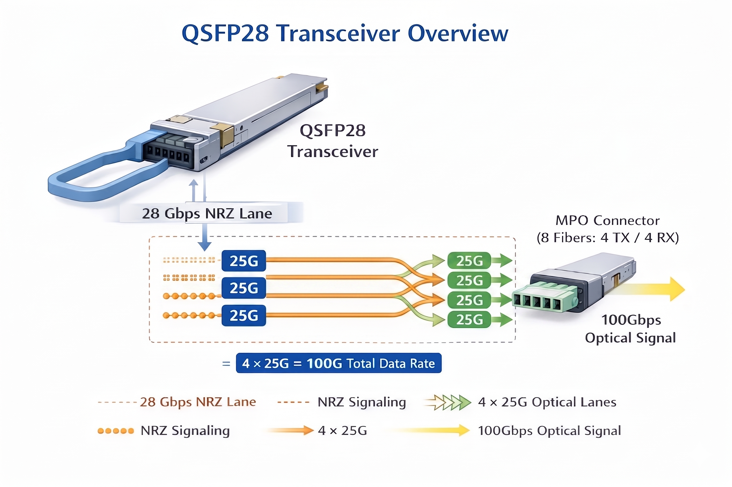
The QSFP28 (Quad Small Form-Factor Pluggable 28) transceiver is a compact optical module designed for high-speed data communication at 100 Gbit/s. The “28” designation refers to the 28 Gbps electrical signaling speed per channel. In practice, each QSFP28 module uses four lanes operating at 25 Gbps NRZ (Non-Return-to-Zero) signaling to deliver a total of 100 Gbps.
Key Technical Specifications of QSFP28 Modules
Every QSFP28 transceiver complies with the QSFP28 MSA (Multi-Source Agreement) and IEEE 802.3bm standards. The module measures 18.35 mm × 72.4 mm × 8.5 mm, enabling high port density in modern switches and routers.
A QSFP28 interface consists of four lanes, each transmitting data at 25.78125 Gbps using simple NRZ modulation. This differs from newer technologies such as QSFP-DD and QSFP112, which use PAM4 modulation to achieve higher throughput over the same number of lanes.
Power consumption typically ranges from 3.5 W to 4.5 W, depending on the module type and reach. All QSFP28 transceivers support Digital Diagnostic Monitoring (DDM), which provides real-time data on temperature, voltage, transmit power, receive power, and laser bias current.
QSFP28 vs QSFP+: Understanding the Difference
Network engineers often need to compare QSFP28 and the older QSFP+ (40G) standard to avoid costly procurement mistakes.
| Specification |
QSFP+ (40G)
|
QSFP28 (100G)
|
| Aggregate Data Rate |
40 Gbps
|
100 Gbps
|
| Lane Configuration |
4 × 10G NRZ
|
4 × 25G NRZ
|
| Lane Speed |
10.3125 Gbps
|
25.78125 Gbps
|
| Electrical Interface |
4×10G
|
CAUI-4 (4×25G)
|
| Power Consumption |
2.5–3.5 W
|
3.5–4.5 W
|
| Backward Compatibility |
N/A
|
Accepts QSFP+ modules
|
Key compatibility note: QSFP28 ports can accept QSFP+ modules and automatically negotiate down to 40G operation. However, QSFP+ ports cannot support QSFP28 modules. This backward compatibility protects existing infrastructure investments during gradual migration.
Learn about 400G QSFP-DD modules for future upgrades →
QSFP28 Module Types: Complete Comparison
QSFP28 transceivers come in different variants to suit varying transmission distances, fiber types, and application requirements. Selection of the right QSFP28 module ensures reliable connections with cost savings.
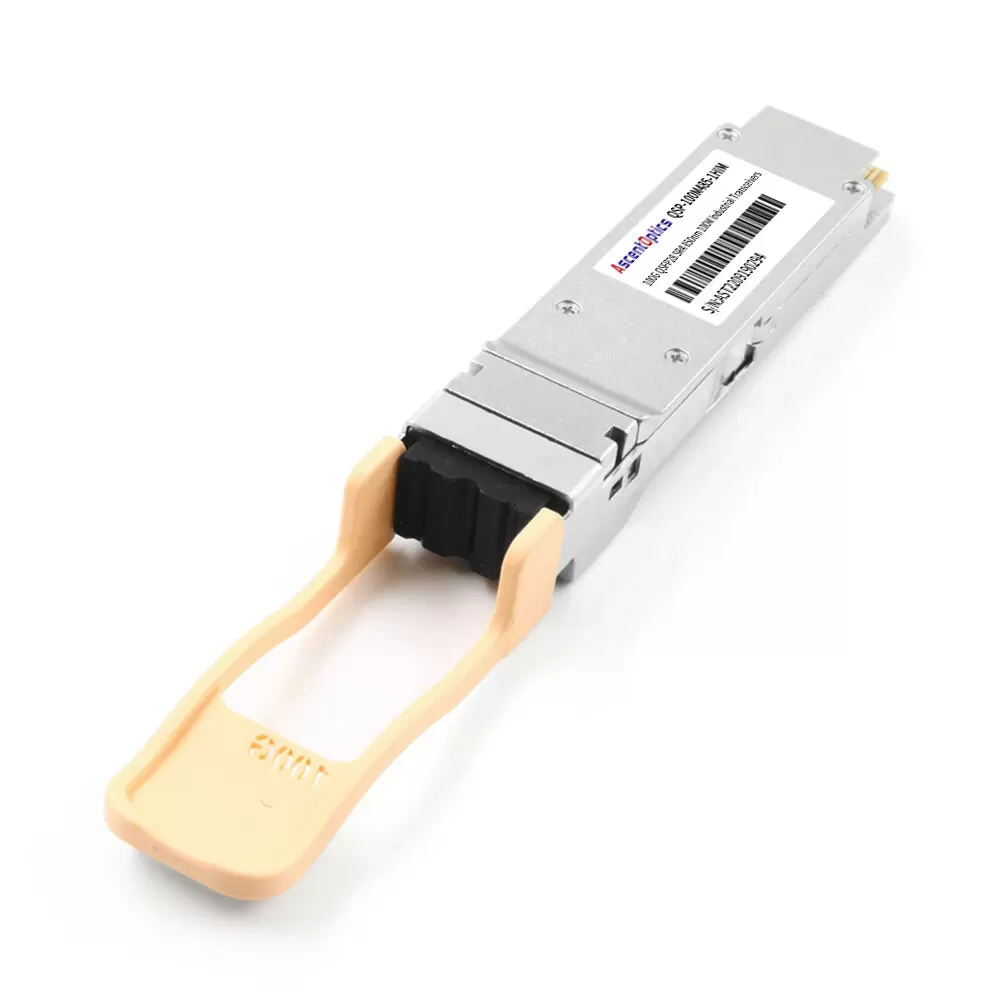
QSFP28 SR4: 100GBASE-SR4 Data Center Standard
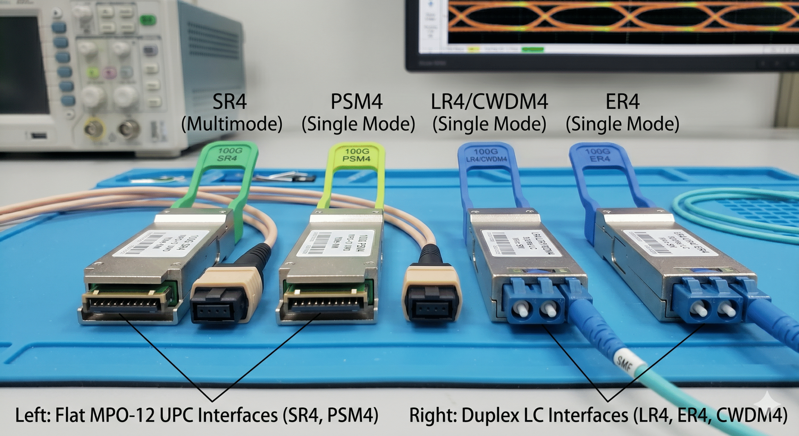
The QSFP28 SR4 (Short Range 4-lane) module is the most commonly used QSFP28 transceiver in data center settings. This type of QSFP28 transceiver employs an 850 nm wavelength for parallel transmission over multimode fiber. The QSFP28 SR4 supports OM4 fiber distances up to 100 m, and OM3 fiber distances up to 70 m, making it an optimal solution in the data center.
An MPO-12 connector is used, with eight fibers active—four transmitting and four receiving fibers—while the remaining fibers are unused. MPO connectors for SR4 are typically flat-polished (UPC), which is suitable for multimode transmission.
Typically, the power consumption for the SR4 is up to 3.5W. This makes it a relatively low-power and cost-effective option, often selected for spine-leaf architectures and server-to-switch connectivity within data centers.
Moving to a new 800-rack center, Marcus Rodriguez, a network architect at a cloud services provider in Singapore, has chosen to adopt the SR4 module. Establishing that “for 95 percent of our intra-DC links, SR4 hits the sweet spot and gives us 100G throughput at the lowest cost per port, with a 100-meter reach that covers most rack-to-rack scenarios according to our design,” Rodriguez shared during the post-deployment review.
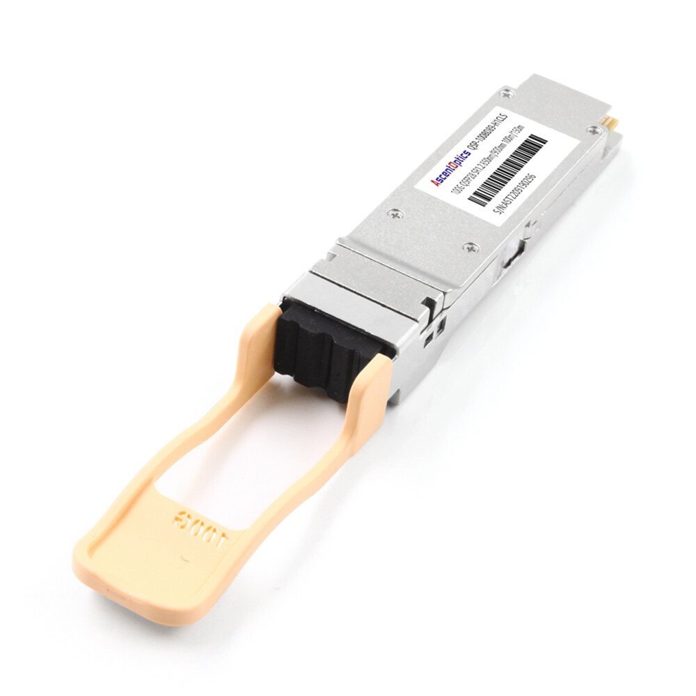
QSFP28 PSM4: 100GBASE-PSM4 Parallel Single-Mode
QSFP28 PSM4 (4 × 25G) provides a cost-effective single-mode solution for links up to 500 meters. It performs parallel data transmission over eight single-mode fibers (four TX and four RX), using an MPO-12 connector.
Compared to wavelength-division solutions, PSM4 avoids the need for multiplexing optics, reducing cost and complexity, but requires more fiber resources.
For PSM4 to be commercially viable, it is best suited for environments where fiber availability is not a constraint and link distances fall within 500 meters.
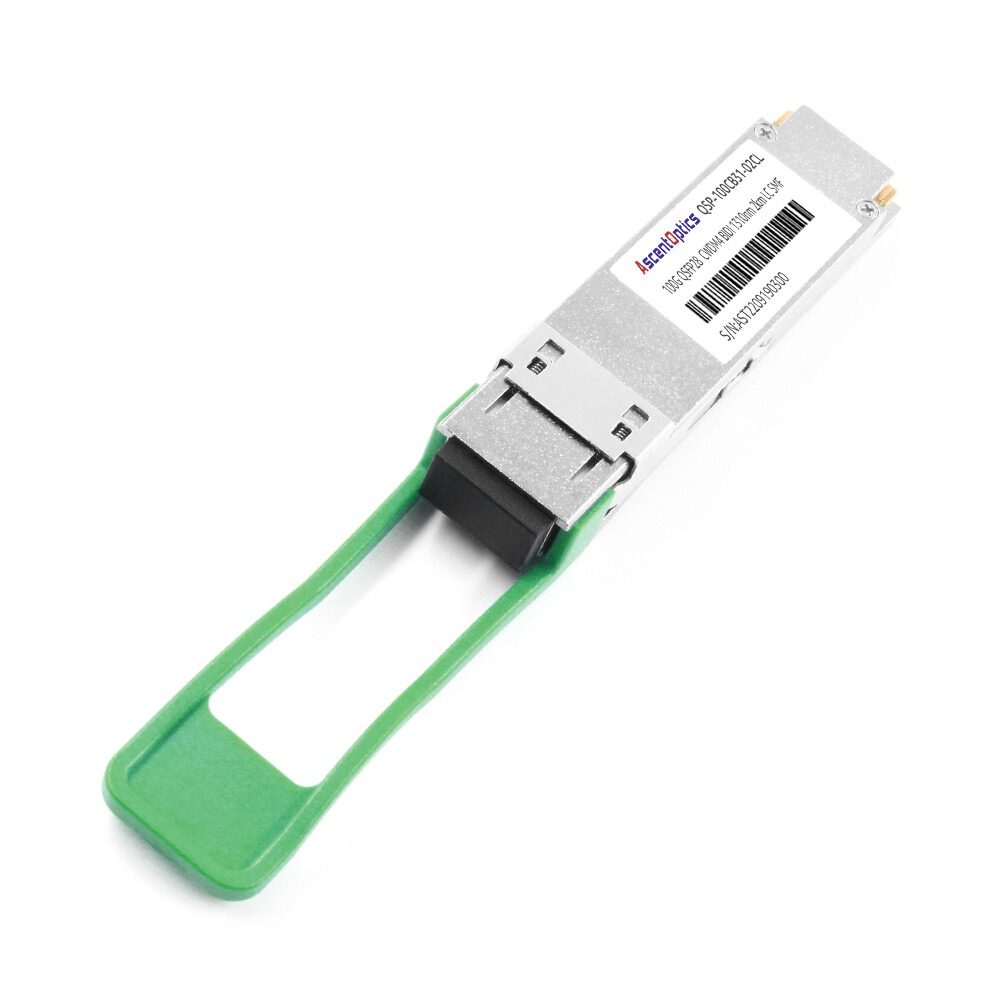
QSFP28 CWDM4: Cost-Optimized Single-Mode
The QSFP28 CWDM4 serves as a compromise between SR4 and LR4, offering up to a 2-kilometer reach commonly required for short-distance data center interconnects. Like LR4, it uses four CWDM wavelengths and operates over duplex LC connectors on single-mode fiber.
The main difference lies in the optical specifications: CWDM4 relaxes certain parameters compared to LR4 to reduce cost while maintaining a 2 km reach. This makes it suitable for a large portion of short-reach DCI scenarios where full 10 km performance is unnecessary.
The power usage of a typical QSFP28 CWDM4 module is around 3.5W to 4W, slightly higher than SR4 but generally lower than LR4 for shorter-distance applications.
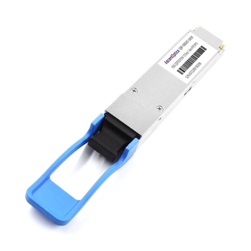
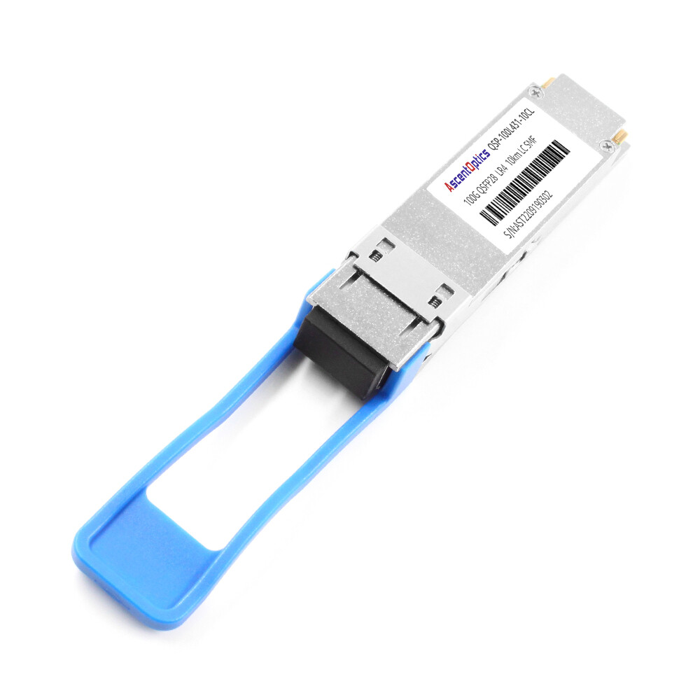
QSFP28 LR4: 100GBASE-LR4 Long-Reach Single-Mode
The QSFP28 LR4 is ideal for interconnections beyond multimode fiber limitations. It uses four CWDM wavelengths (approximately 1295 nm, 1300 nm, 1305 nm, and 1310 nm) to multiplex 4 × 25G lanes onto a single pair of single-mode fibers.
The duplex LC interface simplifies deployment compared to parallel fiber solutions. The QSFP28 LR4 transceiver supports distances up to 10 kilometers over OS2 single-mode fiber and is well suited for DCI, campus, and metro network applications.
QSFP28 LR4 module power consumption typically ranges from 3.5W to 4.5W, depending on the optical design, commonly using uncooled EML or DML lasers.
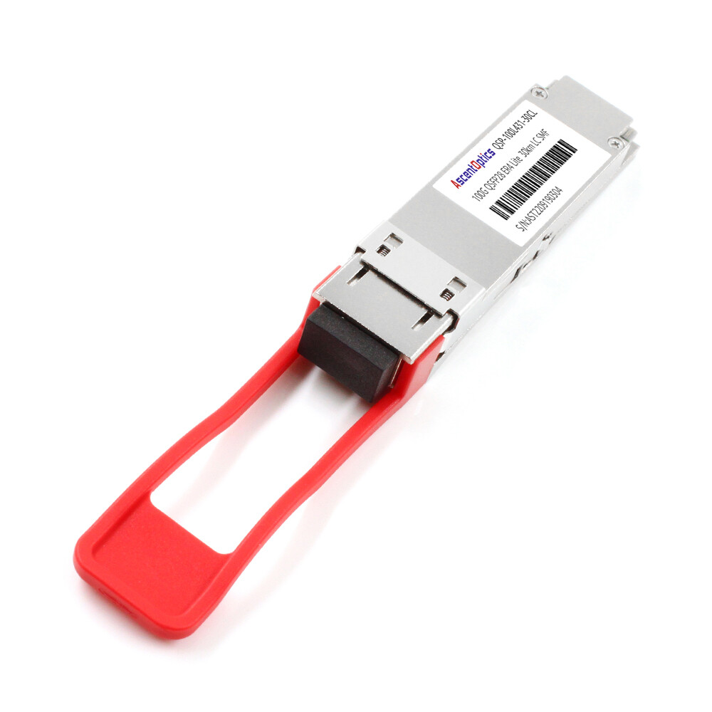
QSFP28 ER4: 100GBASE-ER4 Extended Reach
The QSFP28 ER4 (Extended Range) transceiver extends single-mode transmission up to 40 km using four LAN-WDM wavelengths, similar to LR4 but with higher optical power and more sensitive receivers.
These QSFP28 ER4 modules are widely used in data center interconnect, telecom backhaul, and enterprise WAN connectivity scenarios.
Power consumption for QSFP28 ER4 modules is typically around 4.5W, as they rely on higher-performance optical components, often including cooled EML transmitters to support extended reach.
Module Selection Decision Matrix
| Scenario |
Distance
|
Fiber Type |
Recommended Module |
Typical Cost
|
| Intra-rack |
<10 m
|
MMF |
SR4 or DAC |
$
|
| Data center |
10–100 m
|
MMF |
SR4 |
$$
|
| Campus/DCI |
100 m–2 km
|
SMF |
CWDM4 |
$$$
|
| Long DCI |
2–10 km
|
SMF |
LR4 |
$$$$
|
| Extended |
10–40 km
|
SMF |
ER4 |
$$$$$
|
| Parallel SMF |
500 m
|
SMF |
PSM4 |
$$$
|
Need help selecting QSFP28 modules? Contact our engineers →
QSFP28 Cabling and Breakout Cable Options
In addition to optical transceivers, QSFP28 connectivity encompasses different cable technologies that are suited to various deployment scenarios. Selection of cabling for your QSFP28 transceiver installation impacts both cost and performance.
QSFP28 Direct Attach Copper (DAC) Cables
QSFP28 Direct Attach Copper (DAC) cables provide a low-cost and low-power solution for short-reach interconnects within racks or between adjacent racks. These passive copper cables support 100G transmission over distances typically up to 3 to 5 meters, depending on cable quality and system design.
DAC cables offer near-zero latency and very low power consumption (typically <0.5W), making them ideal for high-density data center environments such as leaf-to-server or leaf-to-leaf connections.
Active DAC (ACC) variants extend reach slightly beyond passive DAC by integrating signal conditioning components, while maintaining relatively low power consumption compared to optical alternatives.
QSFP28 Active Optical Cables (AOC)
AOCs, or Active Optical Cables, integrate optical transceivers directly with fiber cable assemblies, making them a pre-terminated, plug-and-play alternative to discrete optics plus fiber cabling. QSFP28 AOCs typically support distances up to 100 meters.
Compared to DACs, AOCs are lighter, support longer distances, and offer a smaller bend radius. Power consumption is typically around 1–2W per end, which is higher than passive DACs but generally lower than using separate optical transceivers.
AOCs are well suited for structured cabling environments or deployments where ease of installation and cable management are priorities.
Structured Fiber Cabling for QSFP28
For permanent infrastructure, separate fiber cabling used with QSFP28 transceivers provides maximum flexibility and scalability.
Multimode fiber (preferably OM4 for new deployments) is commonly used with SR4 modules for short-reach intra-data-center connections. Single-mode fiber (OS2) is used for longer-reach applications such as CWDM4, LR4, and ER4 deployments.
MPO-12 trunk cables are used for QSFP28 SR4 and PSM4 parallel optics, while duplex LC cables are used for QSFP28 CWDM4, LR4, and ER4 modules.
Proper optical polarity management and connector cleanliness are critical to ensuring reliable performance of 100G QSFP28 links.
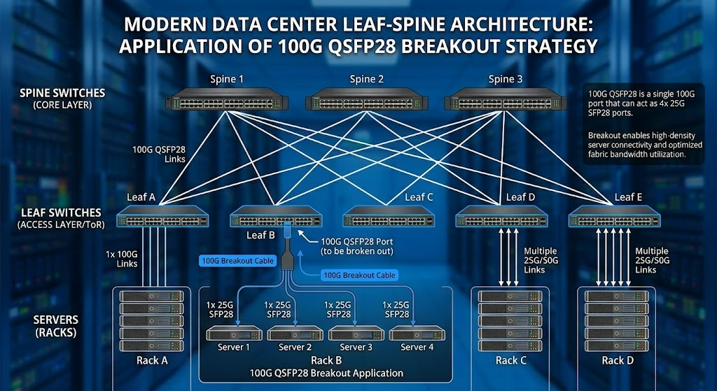
QSFP28 Breakout Cable Strategy
QSFP28 breakout cabling enables a single 100G QSFP28 port to be split into four 25G SFP28 ports, supporting flexible network migration and efficient port utilization.
Using QSFP28-to-4×SFP28 breakout DAC or AOC cables allows four 25G servers to connect to a single 100G switch port, maximizing port density during transition from 10G to 25G server architectures.
This approach is widely adopted in modern leaf-spine architectures, where leaf switches provide 25G server access and spine switches operate at 100G uplinks, making QSFP28 breakout configurations a mature and practical deployment model.
QSFP28 Switch Compatibility Matrix
| Vendor |
Platform
|
QSFP28 Ports |
Breakout Support |
Key Modules
|
| Cisco |
Nexus 9336PQ
|
36 |
Yes |
SR4, LR4, CWDM4
|
| Cisco |
Nexus 93180YC-EX
|
6 |
Yes |
SR4, DAC, AOC
|
| Arista |
7050X3
|
32 |
Yes |
All standard types
|
| Arista |
7280SR2
|
64 |
Yes |
SR4, LR4, CWDM4
|
| Juniper |
QFX5110
|
4 |
No |
SR4, LR4
|
| Juniper |
QFX5120
|
32 |
Yes |
All standard types
|
| NVIDIA |
SN2410
|
8 |
Yes |
SR4, DAC, AOC
|
View our QSFP-DD compatible switches guide for 400G upgrades →
Power Consumption and Thermal Design
100G deployment power planning requires understanding the power characteristics of QSFP28 transceivers and their scaling effect. Power consumption primarily impacts the cooling requirements and operation cost in data center environments.
QSFP28 Module Power Specifications
| Module Type |
Typical Power
|
Maximum Power |
Heat Output
|
| SR4 |
3.5W
|
4.0W |
12-14 BTU/hr
|
| CWDM4 |
3.5W
|
4.0W |
12-14 BTU/hr
|
| PSM4 |
3.5W
|
4.0W |
12-14 BTU/hr
|
| LR4 |
4.0W
|
4.5W |
14-15 BTU/hr
|
| ER4 |
4.0W
|
4.5W |
14-15 BTU/hr
|
| DAC |
0.5W
|
1.0W |
2-3 BTU/hr
|
| AOC |
1.0W
|
1.5W |
3-5 BTU/hr
|
At-Scale Power Planning
A fully loaded 32-port 100G switch with optical modules can also drain 112-144W for optics alone. Therefore, in a 48-switch data center pod, transceiver power alone becomes 5.4-6.9kW.
Heat concentration is indeed the main design priority in this case. Current switches accommodate high-density QSFP28 deployments with back-to-front or front-to-back airflow patterns, but the calculations for addressing thermal management in the ambient, or any rack-level cooling capacity, should indeed be meticulously scrutinized.
Power consumption comparison-The QSFP28 DAC cable, per end capita, consumes 0.5-1.0W compared to 3.5-4.5W for the QSFP28 optical transceiver with 75-85% less power. In power-constrained areas, preferring DACs in the one-meter range eliminates load from the thermal perspective.
DDM Monitoring for Thermal Management
We monitor all modules in real time for evaluation of the temperature. The customer’s domain is acceptable when operating between 0°C and 70°C (commercial grade) or -40°C and 85°C (industrial grade). Keeping parameters like DDM will help to again put the descending of thermal skills in time.
QSFP28 Deployment Best Practices
Successful MPS deployments could benefit from thorough planning on different operational fronts prompting success in terms of reliability and performance-enhancing customer experience and satisfaction over their service life.
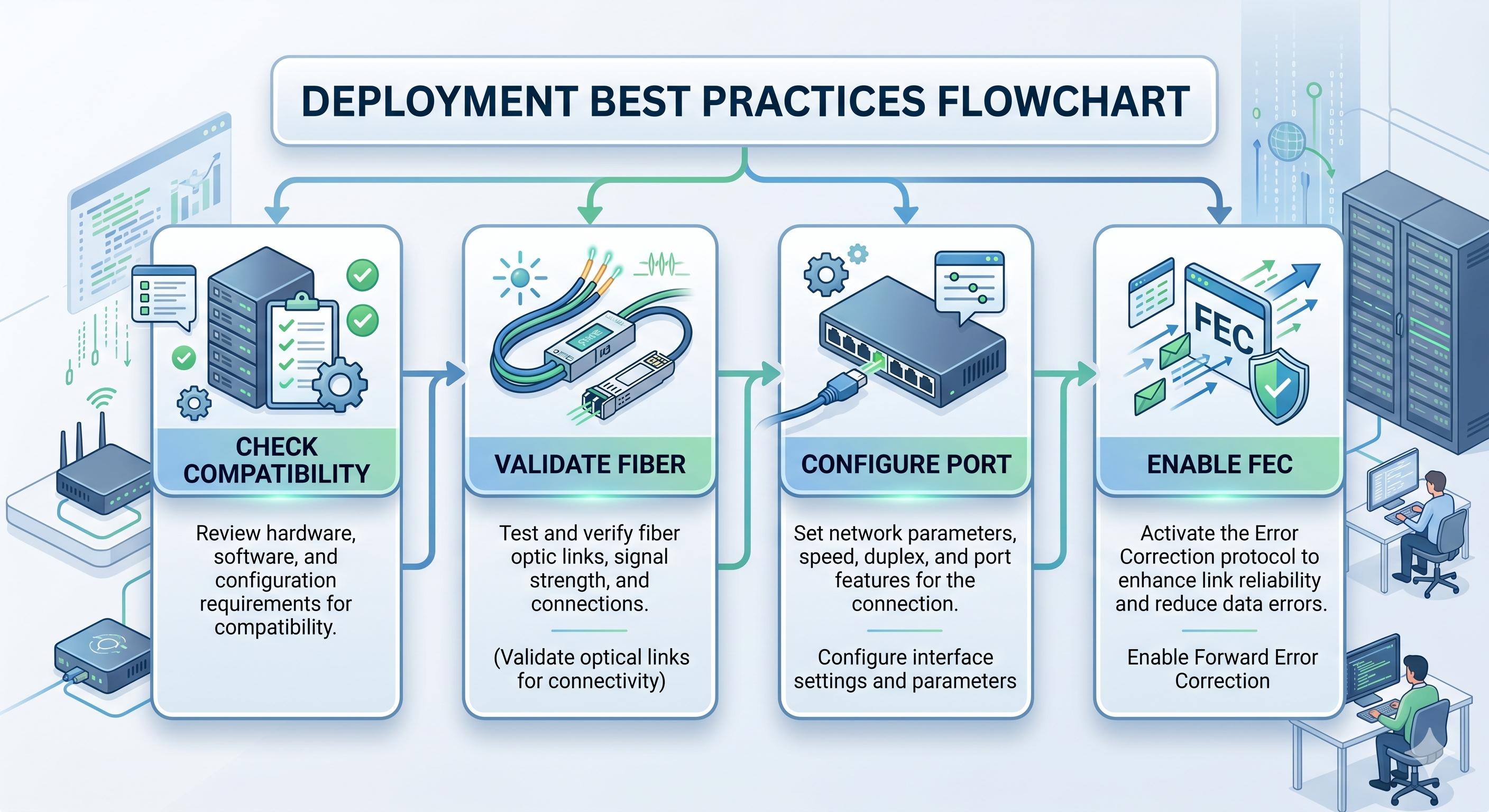
Pre-Deployment Verification
Before installing any QSFP28 transceiver, verify:
- •Switch firmware compatibility: Check vendor compatibility matrices for supported module types and required software versions
- •Fiber infrastructure validation: Confirm fiber type, distance, and connector cleanliness meet module specifications
- •Port configuration: Ensure switch ports are configured for 100G operation, not 40G or auto-negotiation unless intended
- •FEC requirements: Most 100G links require Forward Error Correction (FEC) enabled for reliable operation
FEC Configuration
Forward Error Correction is a crucial requirement for the proper operation of 100G. There are two modes of FEC for QSFP28:
RS-FEC (Reed-Solomon): The standard for 100G Ethernet, providing 7dB of coding gain. Required for SR4, CWDM4, LR4, and ER4 modules on fiber optic links.
Firecode FEC (BASE-R): Lighter-weight FEC used for shorter distances and backward compatibility with 40G modes.
Switch configurations often default to a proper FEC setting but manual verification ensures better link stability. Most systems show the active FEC level when you issue a show interface command.
DDM/DOM Monitoring Implementation
Digital Diagnostic Monitoring tracks five critical parameters:
- •Temperature: Module operating temperature in Celsius
- •Voltage: Supply voltage (nominal 3.3V)
- •TX Power: Transmit optical power in dBm
- •RX Power: Received optical power in dBm
- •Laser Bias Current: Drive current for optical transmitters
Implement monitoring thresholds to trigger alerts before degradation causes failures. Typical thresholds:
| Parameter |
Warning Low
|
Warning High |
Alarm Low |
Alarm High
|
| Temperature |
-5°C
|
70°C |
-10°C |
75°C
|
| TX Power (SR4) |
-9.5 dBm
|
-1.0 dBm |
-11.0 dBm |
1.0 dBm
|
| RX Power (SR4) |
-11.0 dBm
|
-1.0 dBm |
-13.0 dBm |
1.0 dBm
|
Cleaning and Maintenance
Optical connectivity at 25G lane speeds is unforgiving of contamination. Follow these procedures:
- 1. Inspect before connecting: Use a fiber inspection microscope to verify connector cleanliness
- 2. Clean if contaminated: Use lint-free wipes and appropriate solvent for the connector type
- 3. Protect unused ports: Keep dust caps installed on open transceivers and cable connectors
- 4. Document baseline DDM readings: Record initial readings for future comparison
Troubleshooting Common Issues
| Symptom |
Likely Cause
|
Resolution
|
| Link won’t establish |
FEC mismatch |
Verify FEC configuration on both ends |
| High error rates |
Dirty optics |
Clean and inspect fiber connectors |
| Intermittent flapping |
Temperature issues |
Check airflow and cooling |
| Low RX power |
Fiber loss |
Test fiber plant, check for bends |
| Module not recognized |
Firmware incompatibility |
Upgrade switch firmware |
Read our complete QSFP-DD troubleshooting guide →
Migrating to 100G QSFP28 Transceivers from 10G/40G
Organizations with an already 10G/40G infrastructure find themselves in a decision-making dilemma: Sequence and strategy for their upgrades now. Many a time, questions arise about QSFP28 vs. QSFP+ compatibility, which is one aspect. QSFP28’s backward compatibility principle makes it a viable avenue for a phased transition that will avoid dead investment in the current setup.
Migration Pathways
From 10 G SFP+ to 25G SFP28 to 100G QSFP28: the standard step of doubling bandwidth with each movement while recycling infrastructure. Servers will go to 25G SFP28 NICs. Switches will converge 25G access ports into 100G QSFP28 uplinks over breakout cables.
From 40G QSFP+ to 100G QSFP28 upgrade: When comparing QSFP28 against QSFP+, there is a critical difference. When moving from QSFP+ to SFP28 to QSFP28, 40Ghub exchanges will actually keep going to give us a path of access to 100Ghub down the line – by changing the individual 40G ports into 100G QSFP28 transceivers as budget constraints and specific expectations allow.
QSFP28 Breakout Cable Migration Strategy
The QSFP28-to-4×SFP28 breakout pattern enables the most flexible migration path:
- 1. Deploy 100G-capable switches with QSFP28 ports
- 2. Connect existing 10G/25G servers via QSFP28 breakout DAC or AOC cables
- 3. Upgrade servers to native 100G as requirements demand
- 4. Repurpose breakout cables for new 25G connections
This approach maximizes port utilization during transition phases and eliminates stranded capacity.
Cost Considerations
Module pricing follows a predictable hierarchy:
- •DAC cables: $50-150 per link
- •SR4 modules: $150-400 each
- •CWDM4 modules: $400-800 each
- •LR4 modules: $800-1,500 each
- •ER4 modules: $1,500-2,500 each
Infrastructure costs include fiber plant upgrades (OM3 to OM4, or multimode to single-mode) and switch platform investments. A well-planned migration spreads these costs across multiple budget cycles while delivering incremental bandwidth improvements.
Conclusion
There exist QSFP28 transceivers as prevalent module types for 100G Ethernet. These modules, collaborating with numerous switch platforms, and cabling options, have established a mature ecosystem. Knowledge about the distinctions among QSFP28 SR4, QSFP28 LR4, QSFP28 CWDM4, and their variants is mandatory in choosing the proper QSFP28 transceiver for each network link.
Key takeaways for your next QSFP28 deployment:
- •QSFP28 ports accept 40G QSFP+ modules, protecting infrastructure investments during migration
- •SR4 serves 95 percent of intra-data center needs at the lowest cost point
- •CWDM4 hits the sweet spot for 2km data center interconnects
- •Breakout cables enable gradual migration from 25G server infrastructure
- •FEC configuration and DDM monitoring are essential for reliable operation
- •Power and thermal planning must account for 3.5-4.5W per optical module
As you build new hyperscale infrastructure or improve existing large enterprise networks, the building of an optimal QSFP28 transceiver strategy requires striking a balance between performance needs, distance limitations, and pricing. Now, is a pretty good moment on the calendar to delve into the 100G realm, because backward compatibility of the QSFP28 module ecosystem, as well as its greater maturity, neatly puts 100G fingers at everyone’s beck and call.
Request a quote for QSFP28 transceivers tailored to your network →
Frequently Asked Questions
Q1. QSFP28 and QSFP+ Comparison: What Are the Differences?
In the QSFP28 vs. QSFP+ comparison, the QSFP28 transceiver enables 100G Ethernet (4×25G) while QSFP+ supports 40G Ethernet (4×10G). A QSFP28 port will accept QSFP+ modules but can only auto-negotiate to 40G; QSFP+ port cannot support QSFP28 transceivers.
Q2. Can I Use QSFP28 Modules in a 40G Switch?
No. QSFP28 modules require switch ports with 25G SerDes capability. 40G switches use lower-speed 10G SerDes, so they are unable to support higher speeds on multiple lanes needed by QSFP28.
Q3. Which type of fiber will be perfect for QSFP28 SR4?
The multimode fiber is best suited for a QSFP28 SR4 transceiver (OM4 grades preferred and OM3 compatible) with MPO-12 connectors. The maximum distance achievable with this QSFP28 module are 100 meters over OM4 and a distance of 70 meters over OM3.
Q4. Are FECs a necessity for QSFP28 connections?
Yes. Most 100G links have RS-FEC enabled for error control and reliability. So, short DAC cables might go without FEC at low distances, but in every module for optical links, FEC becomes obligatory.
Q5. What will be the maximum QSFP28 LR4 link distance?
A QSFP28 LR4 transceiver supports a maximum of 10 kilometers using single-mode fiber (OS2) at 40 Gbp using LC Duplex connectors. In cases when the distance exceeds 10 km, you can use QSFP28 ER4 for 40 kilometers.
Q6. Can I break out a 100G QSFP28 port to four 25G connections?
Certainly! The same QSFP28 breakdown cable that goes from QSFP28 to 4X SFP28 (DAC or AOC) cables can take the single 100G QSFP28 port transceiver and split it into four 25G links. The QSFP28 breakout cable connection style is a common practice for server connectivity in modern data centers.
Post Views: 1,392